Home › Forums › All Things 750 Twin › Projects and Progress › New Projects › Z750B1 1976
- This topic has 23 replies, 3 voices, and was last updated 7 years, 7 months ago by
 Ownthesky2010.
-
AuthorPosts
-
30th October 2018 at 7:34 pm #24370
 Ownthesky2010Participant
I decided to finish the brake parts next. I couldn’t get the rear caliper off without forcing the piston back in so I will wait until I take the back wheel off for that but I finished off the other bits of the brakes. First the front splitter
I bought a scotch brite wheel for my drill and used that after an alkaline soak and this is the result.

Then light assembly with new stainless banjo bolts and a freshly plated bracket. I also re-plated the sensor but didn’t take any photos.
Next I did the same to the rear master cylinder. This got new main and cup seals matched up from ebay and a bit of reassembly. I didn’t spend the big bucks on the official rebuild kit as there were other kits that used the same 5/8″ seals. Turned out great I think.

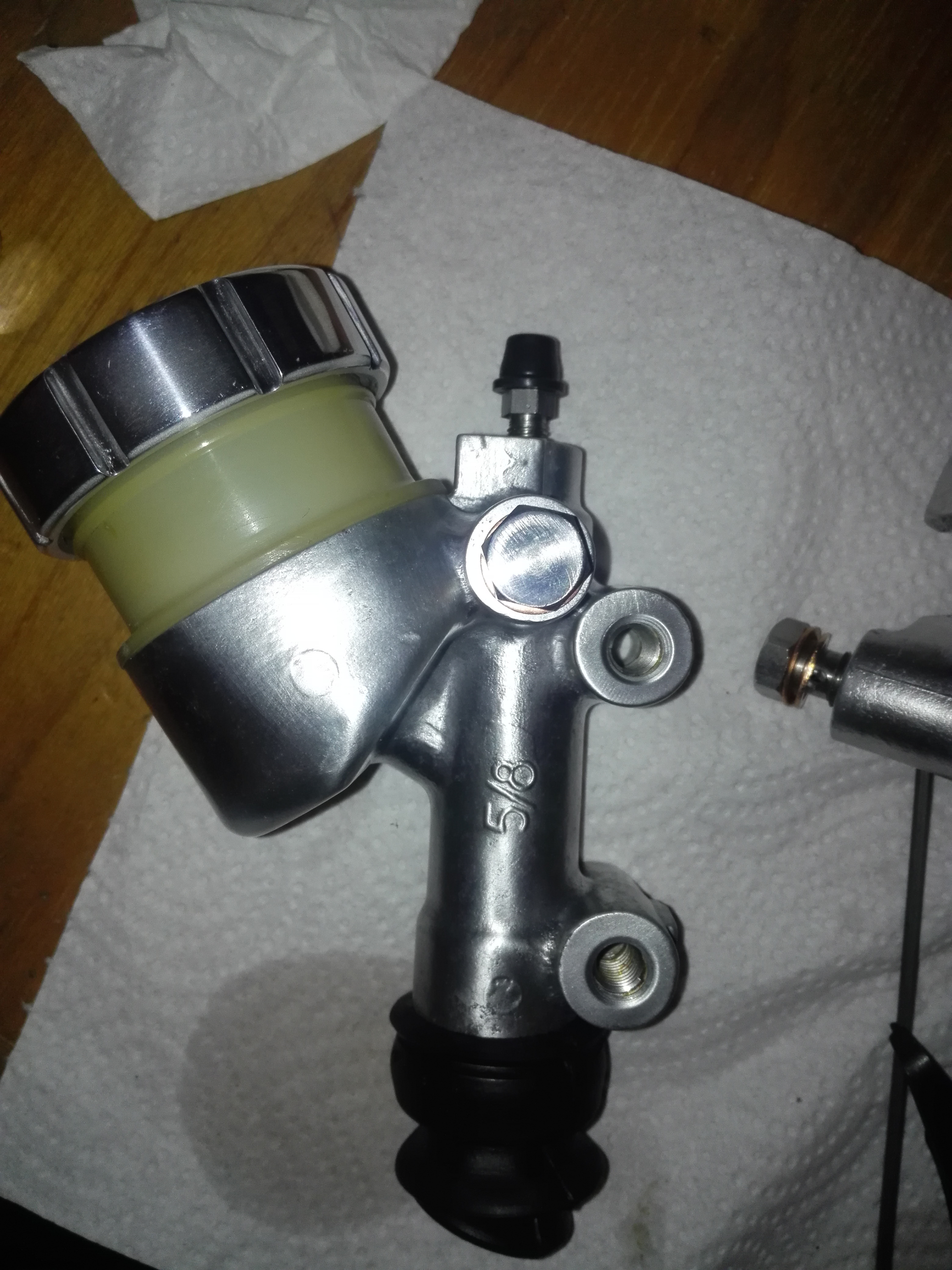
Rear shocks next
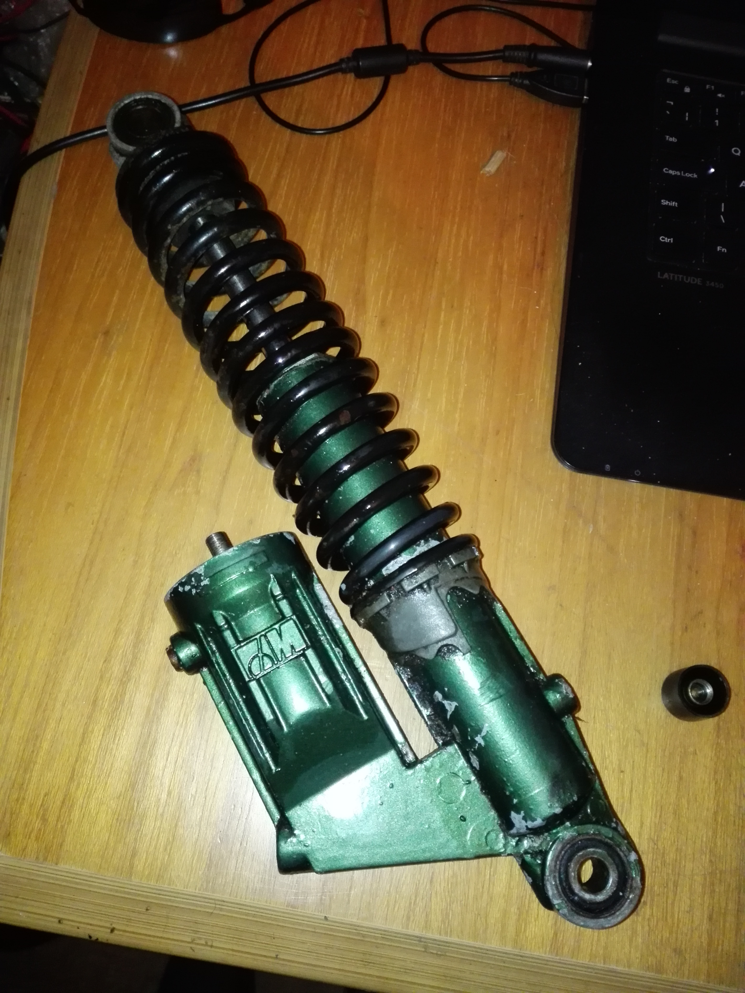
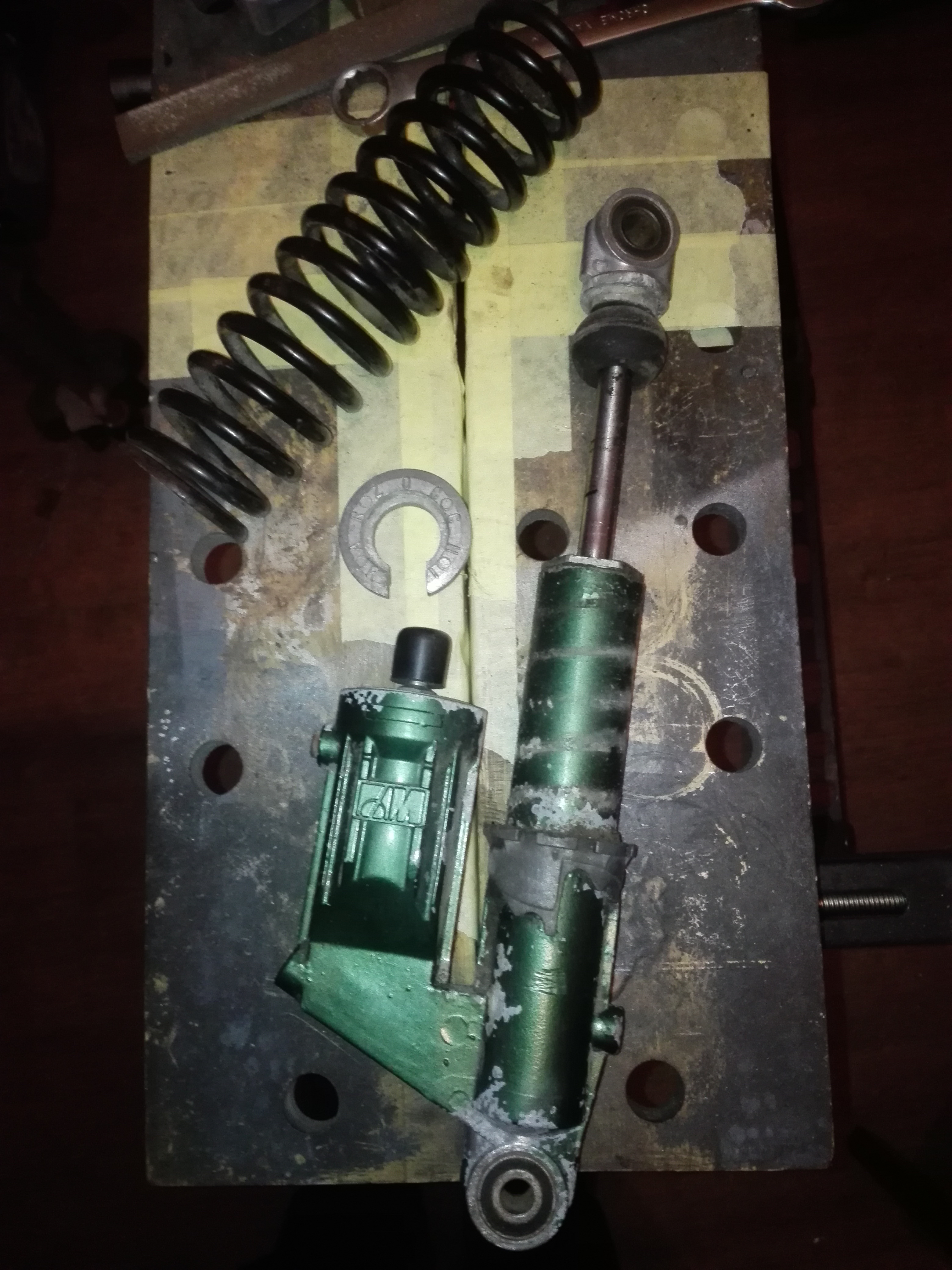
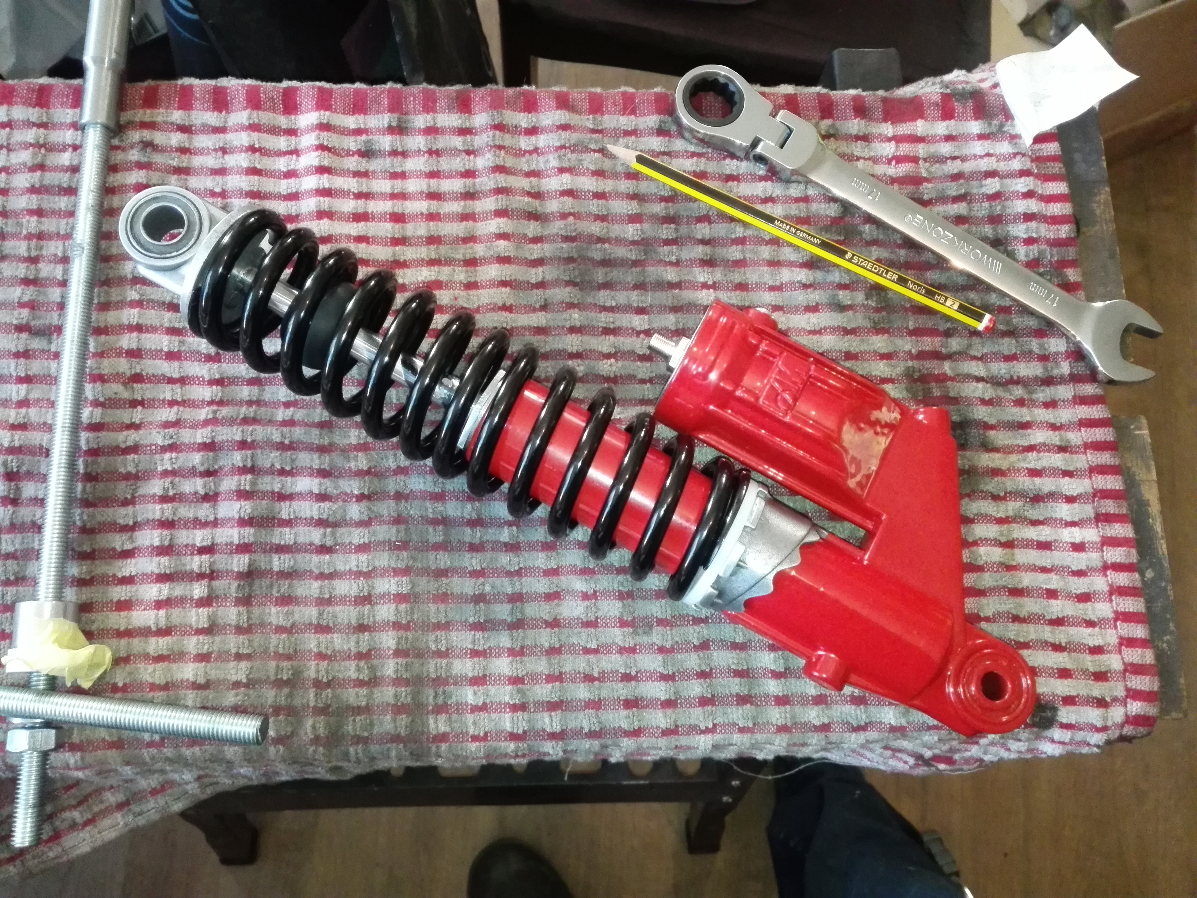
30th October 2018 at 8:17 pm #24371Ownthesky2010ParticipantNext I decided to tackle the rear shocks. These are Marzocchi Strada shocks that were often fitted as standard equipment on Italian bikes of the era. They were sometimes fitted as upgrades so I decided to keep them and do them up. They are rebuildable if the chrome on the shaft is still good but the kit costs £300 and a new set of RFY shocks would cost £65 so I will just replace them if they are in bad condition. I decided to do them one at a time so I can still wheel the bike around as required.
This is as it came off the bike.
It got a good clean and I knocked up a few bits to make a spring compressor.
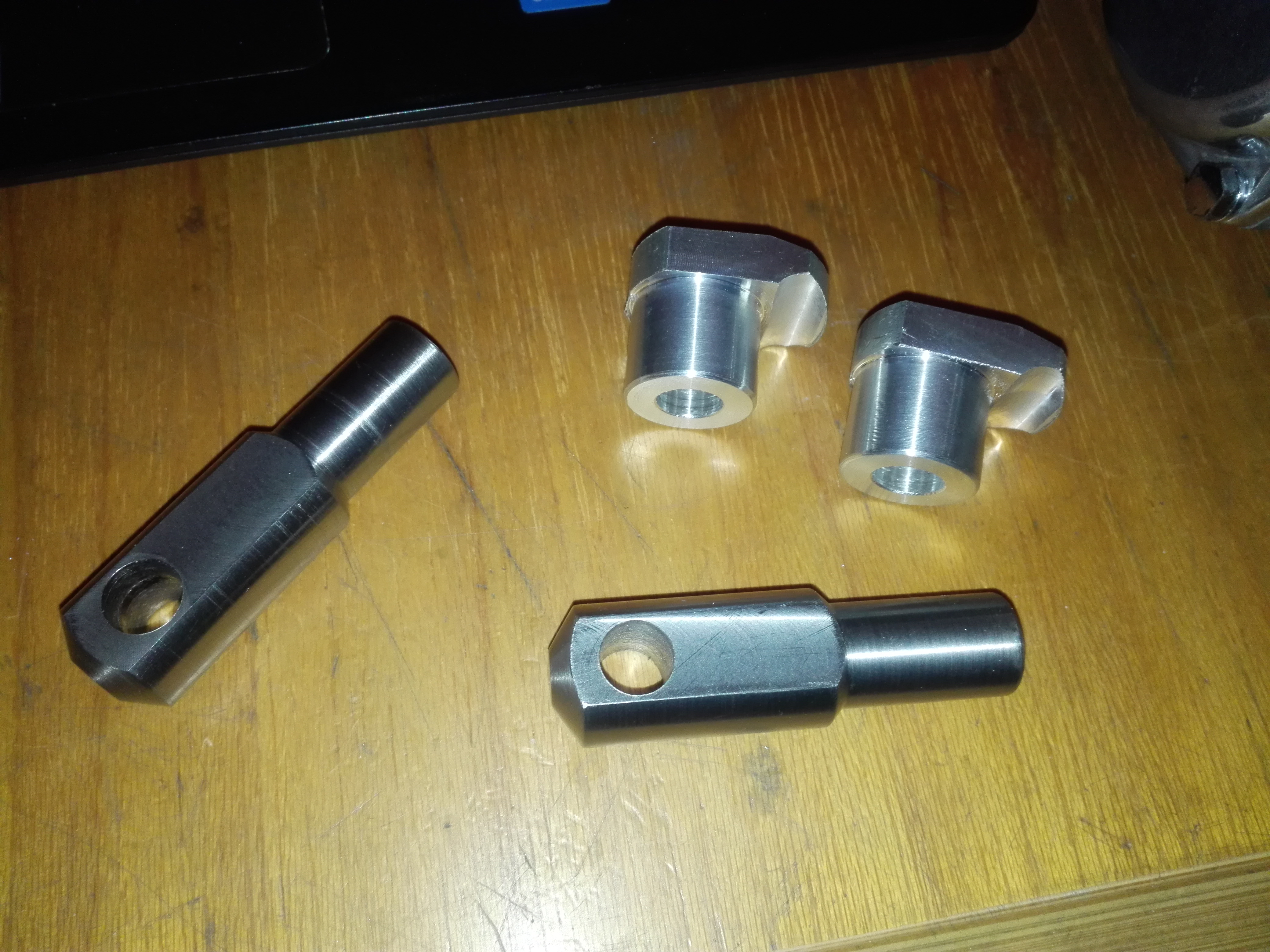
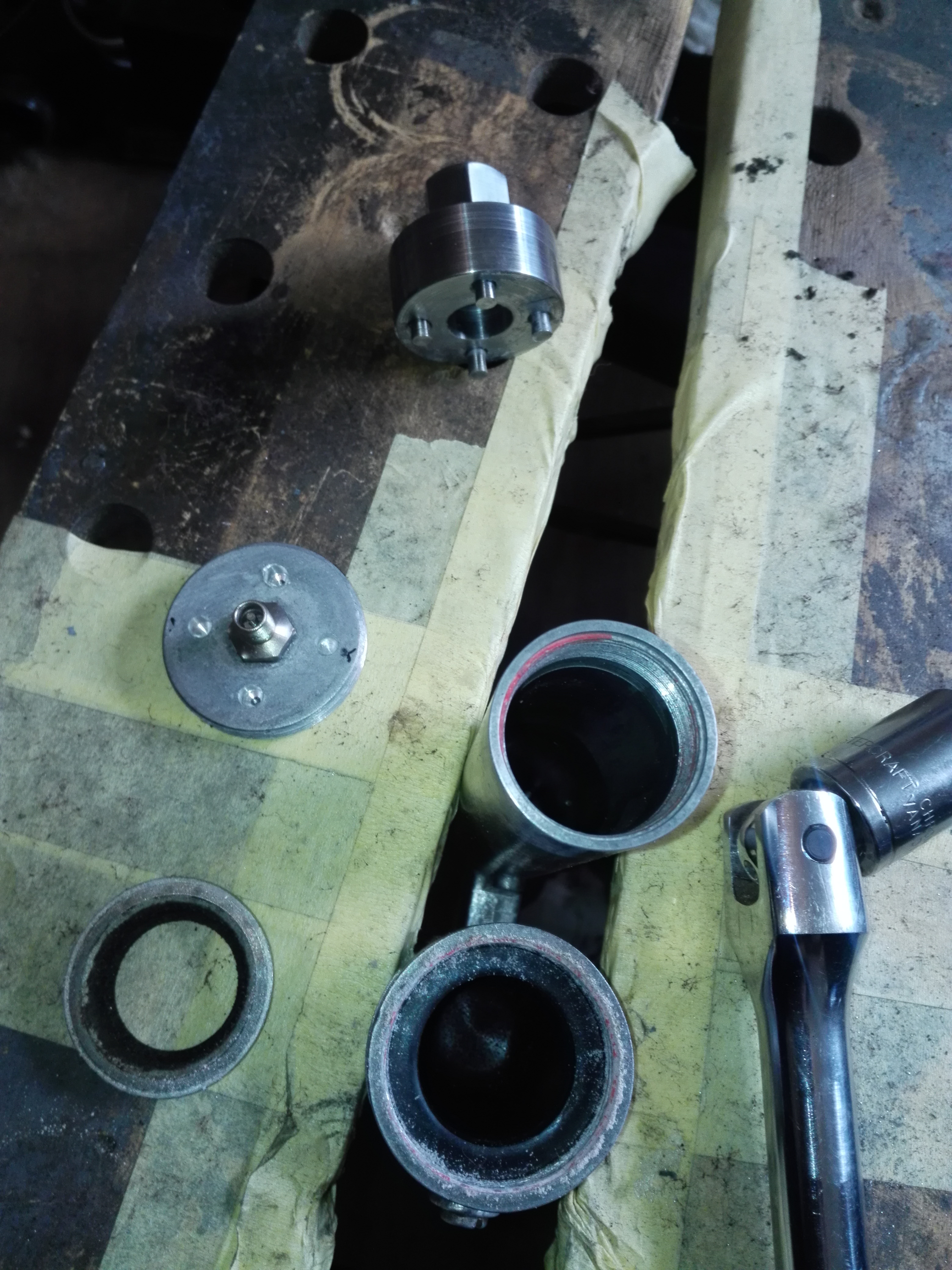
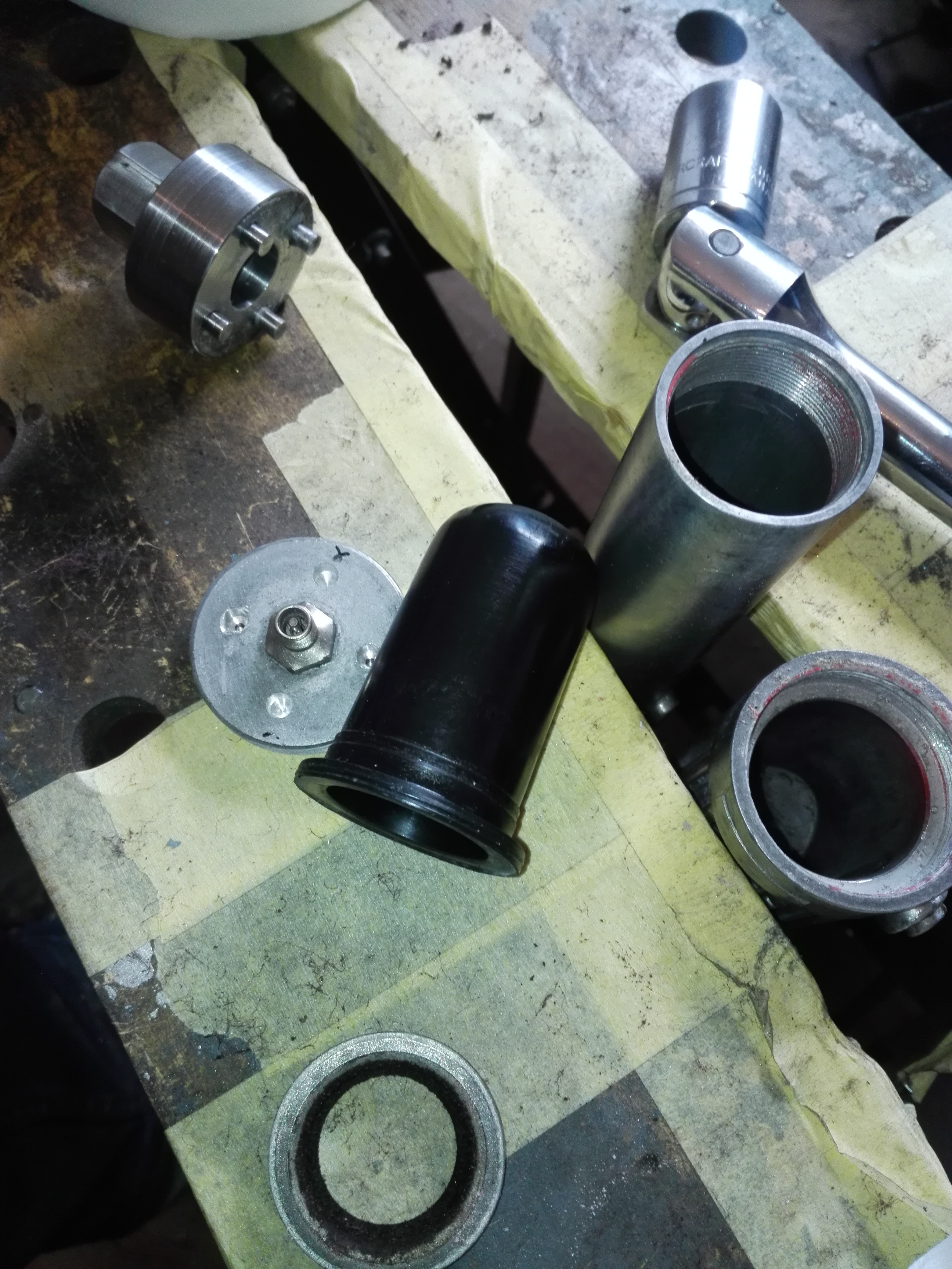
Next I used a 32mm spanner to remove the nut and get all the guts out. The shaft was ok but the main seal was quite hard. I tried to match up a seal but they use a rotary seal instead of a linear one so I just purchased a pair of seals with the same dimensions. The lip is a bit lower but I think it will work. At this point I tried to remove the cap from the gas cylinder part and it was seized solid. I was using and adjustable pin spanner for an angle grinder which wasn’t working so I decided to make a special socket. I drilled out the holes on the cap a little bigger to repair the damage to them and added another 2 holes to increase the drive surface area.
Here are a few photos of the process of turning an old bolt head into a special socket.
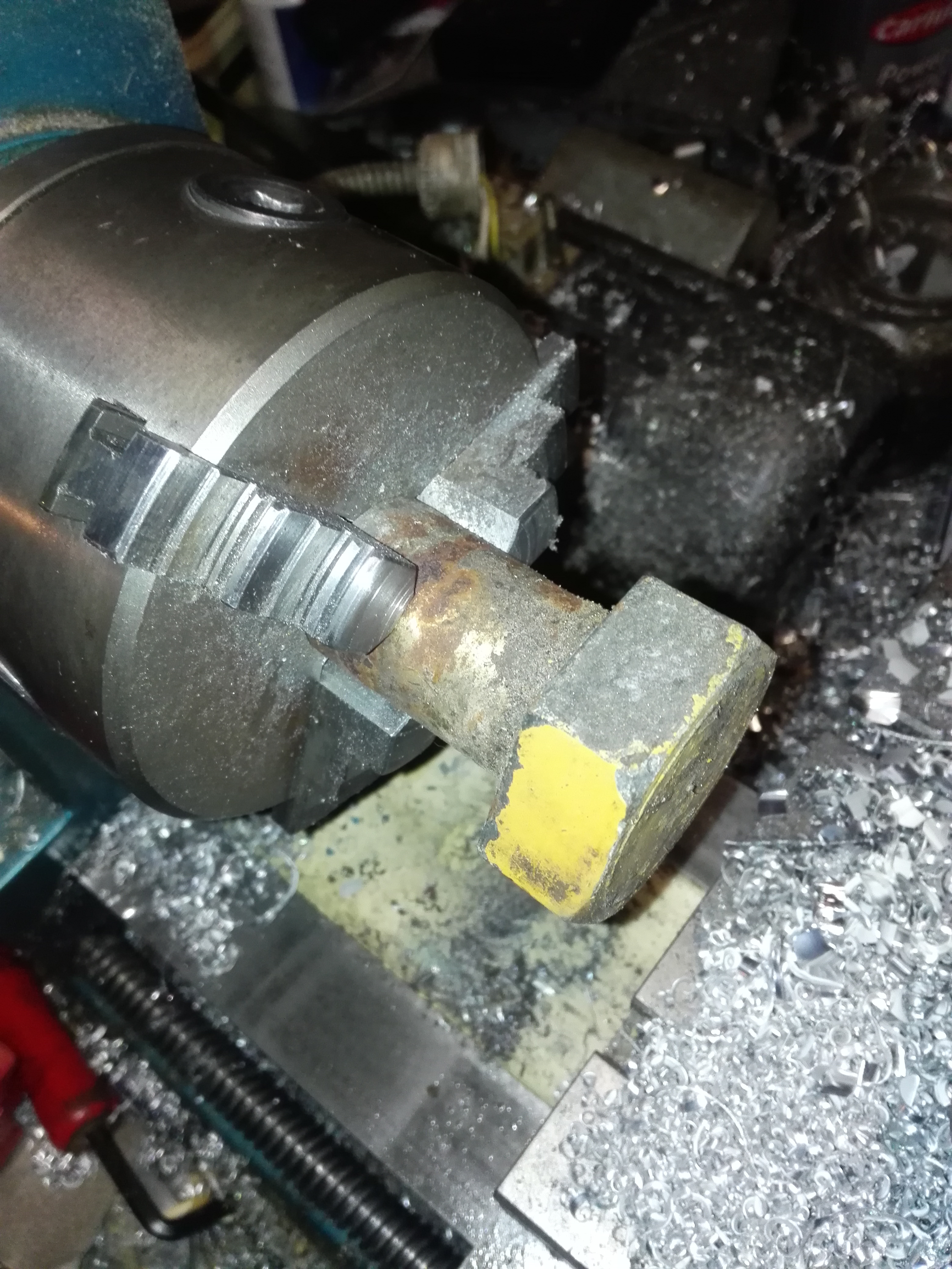
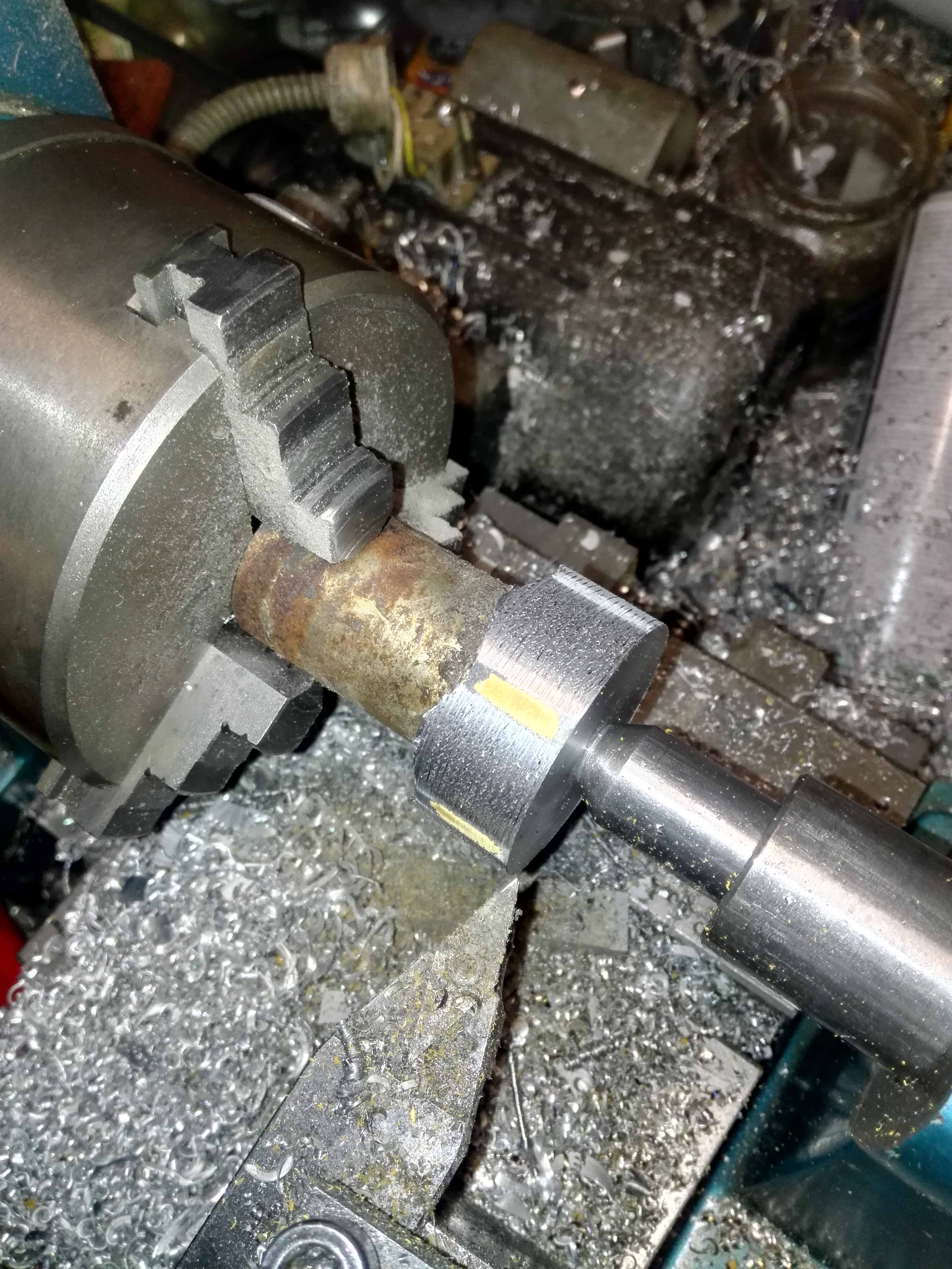
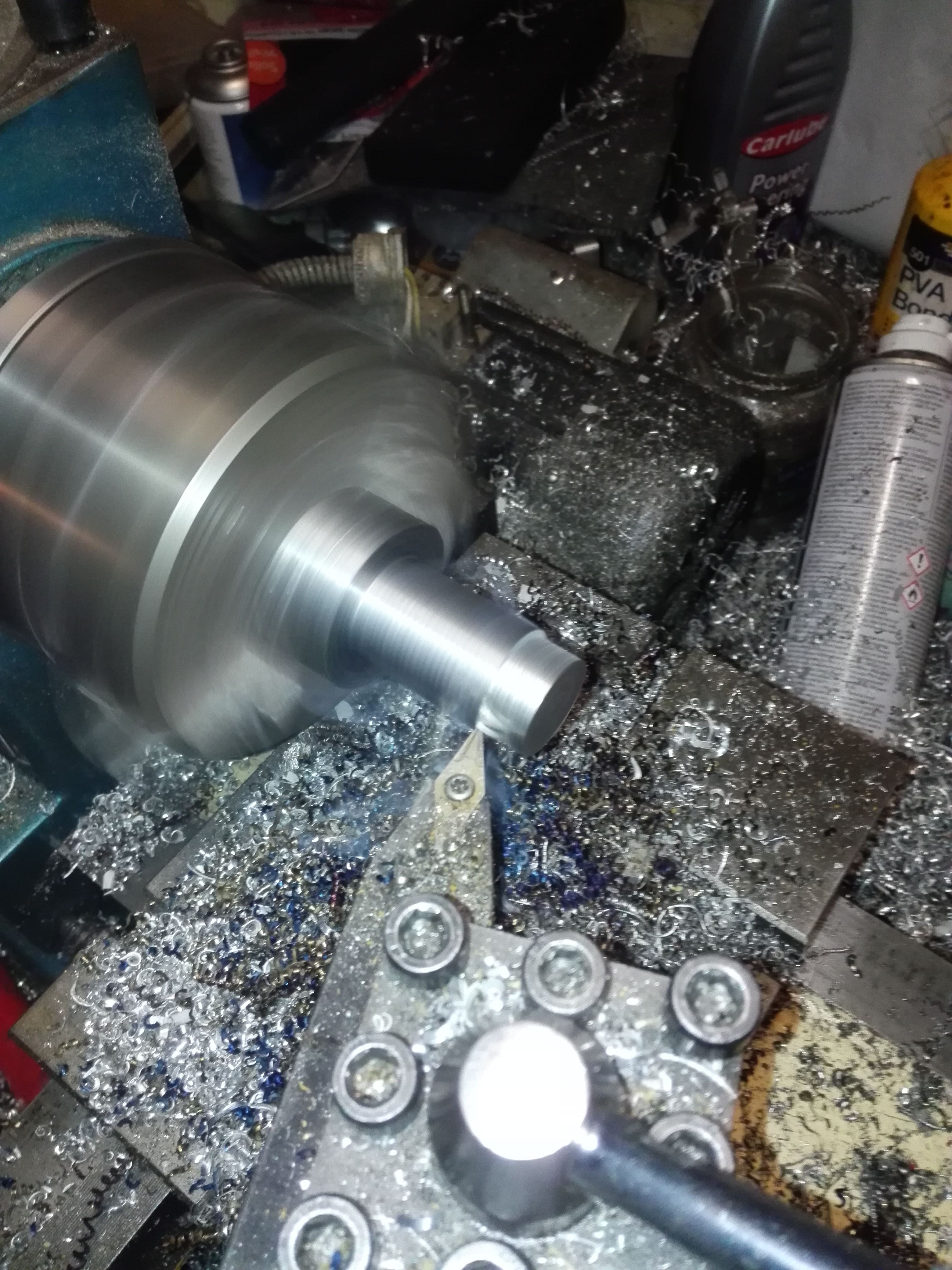
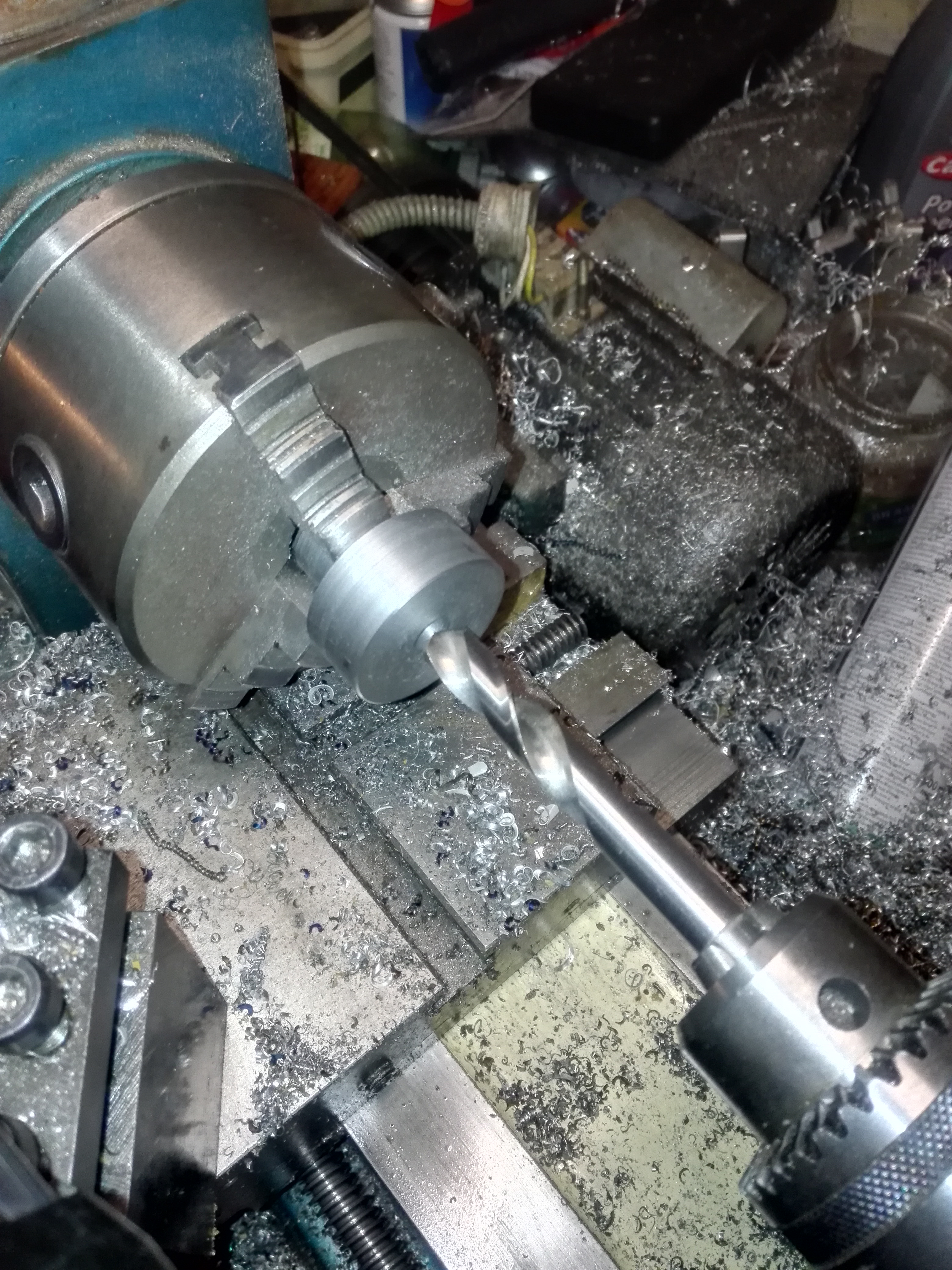
I did the hex in my milling machine and then drilled it for the pins. I had planned to just use super glue to hold in the pins but I decided to leave them loose so I could use the socket as a drill jig to add the extra holes in the other shock.
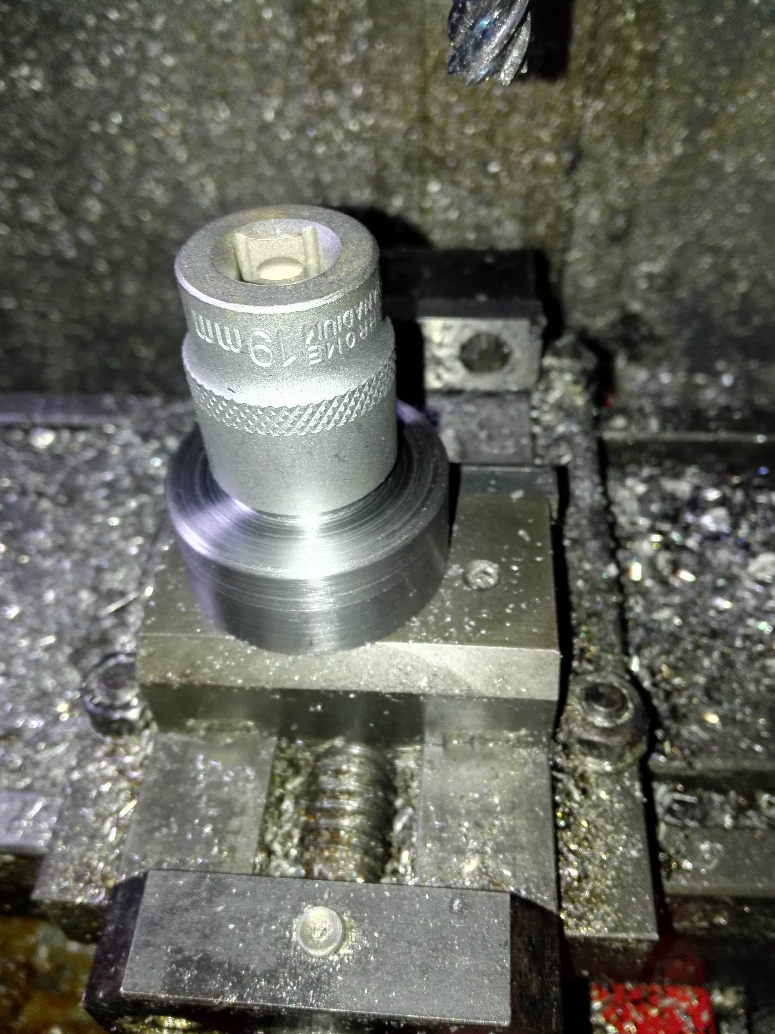
The hex is 19mm
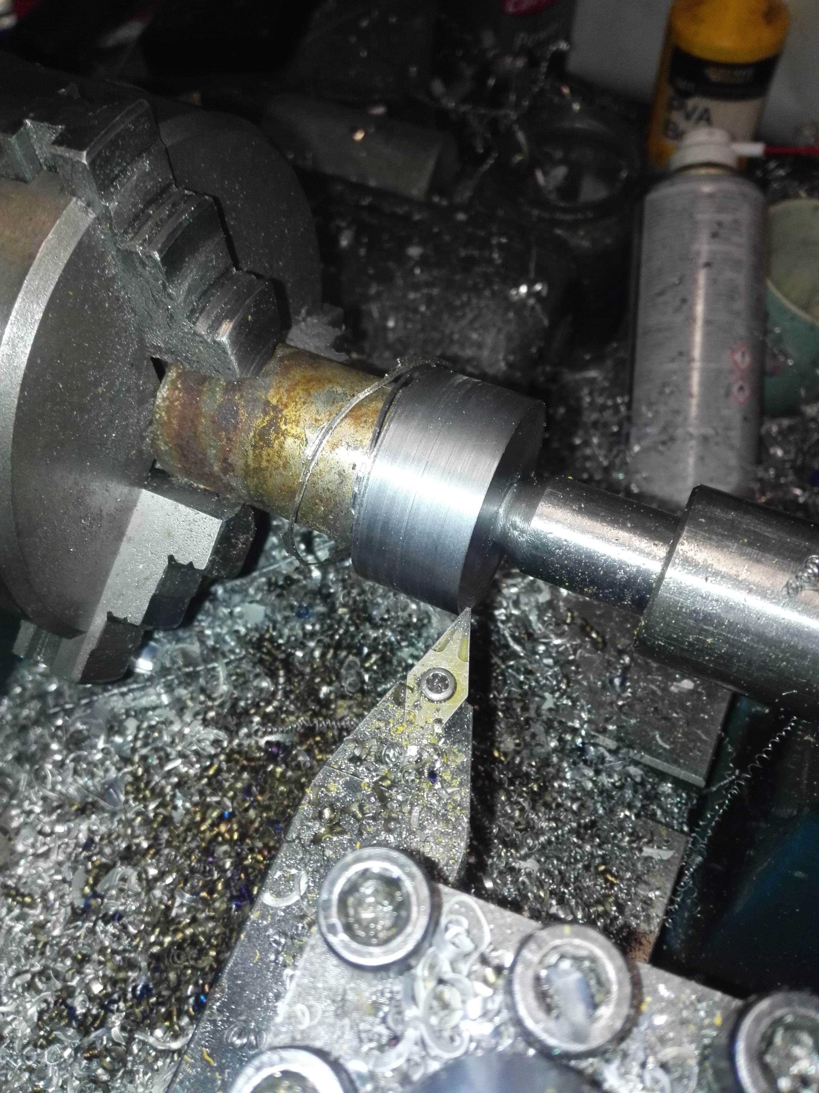
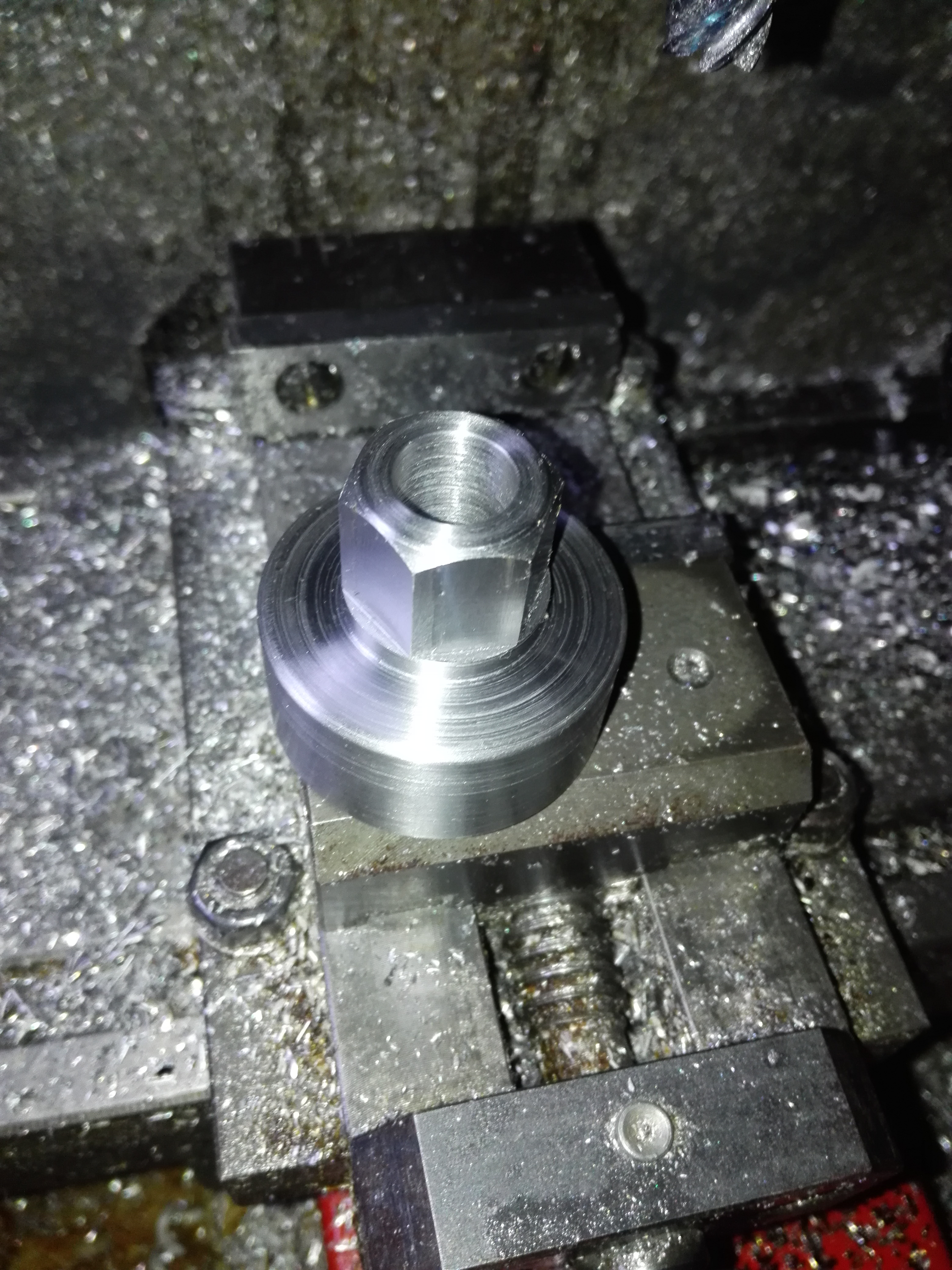
Here it is with its holes
And with the pins mounted. I machined the pins to a slight dovetail so they bite in under pressure and wont slip out. I managed to mess super glue allover the place but it will all just clean off.
Here it is in use.
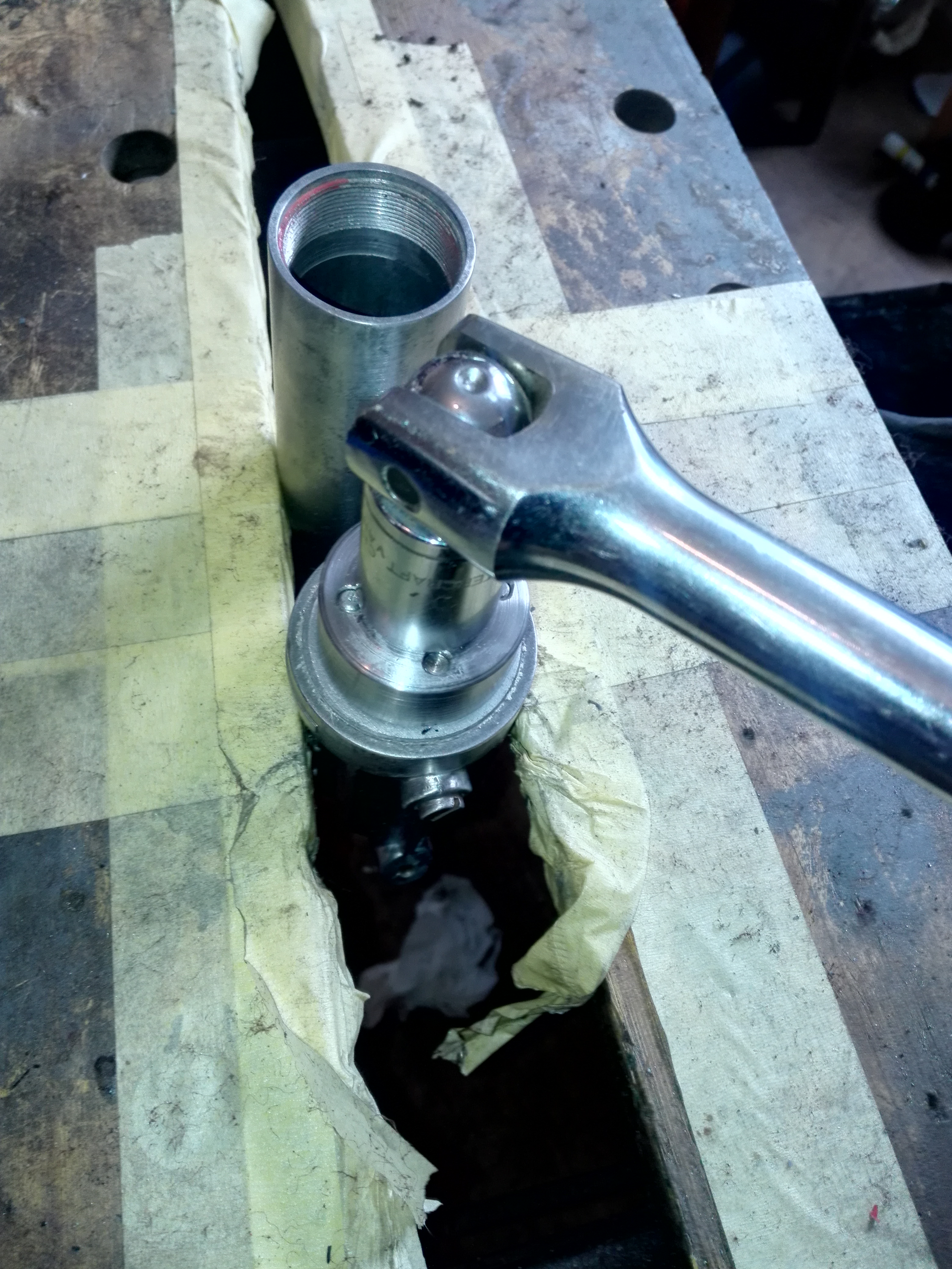
The cap was very tight so I used a long bar and a lot of force but eventually it gave up and came loose. You can see the modified cap in this picture. This modification worked very well.
The bladder turned out to be free of leaks and in good condition. Hopefully the other one is the same.
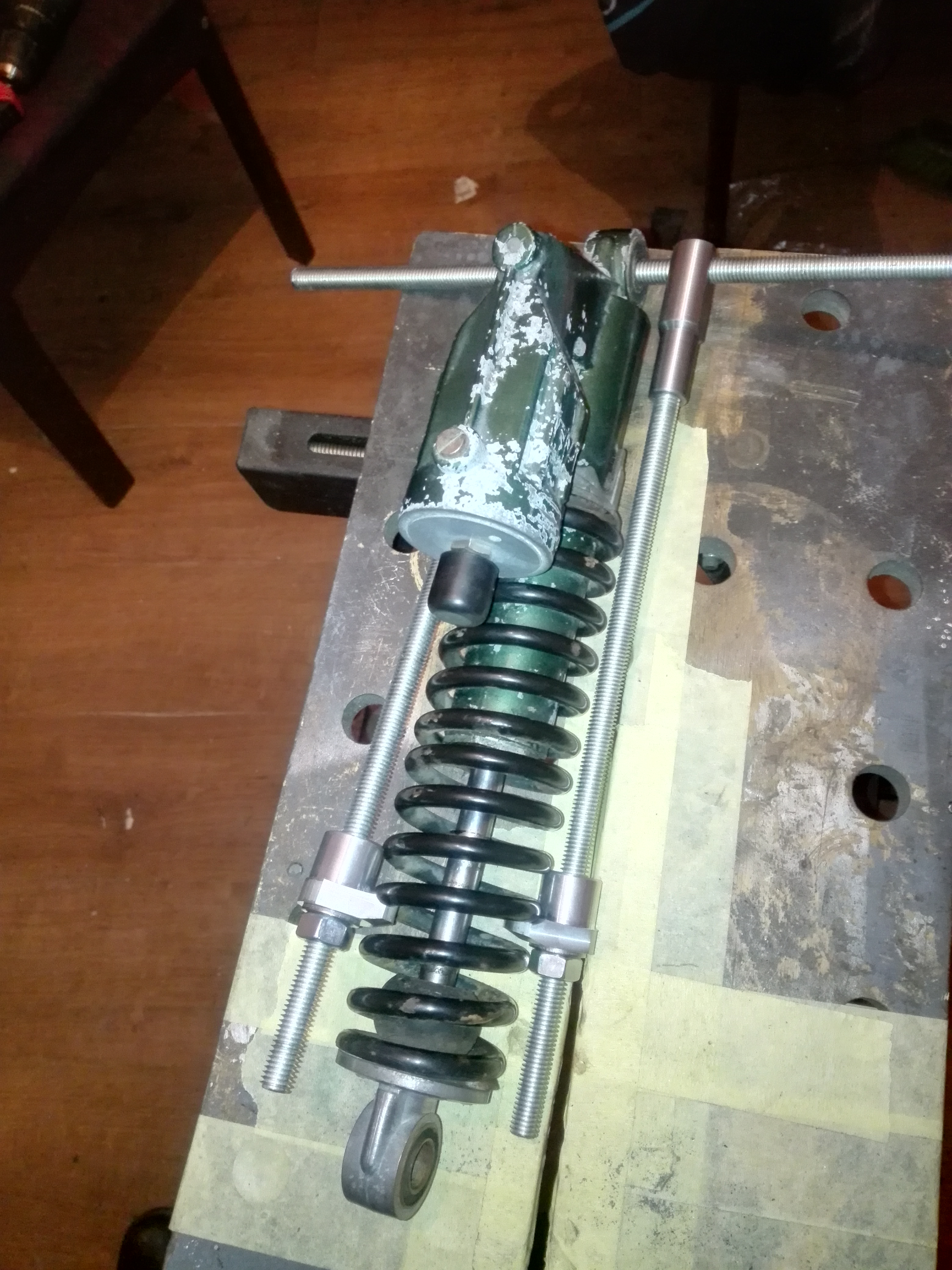
Next the bodies were stripped and painted with more Aldi paint. All the photos I have seen of these are red so that’s what I used. Its not an exact paint match but looks pretty good. The springs were sanded and repainted black and the aluminium parts given a scotch brite treatment. I didn’t strip all the paint off the springs as I know it can be difficult to get the paint even on the inside of the coils and I didn’t want to put it on so thick it would take weeks to dry. I also didn’t like the way the preload adjuster wobbled around on the body and it looked like the spring would be rubbing the body too so I decided to make a spacer to align them. You can see it in the following picture. It adds 4mm to the height so it will result in slightly higher preload but I will assemble these on their lowest setting and see how it goes.
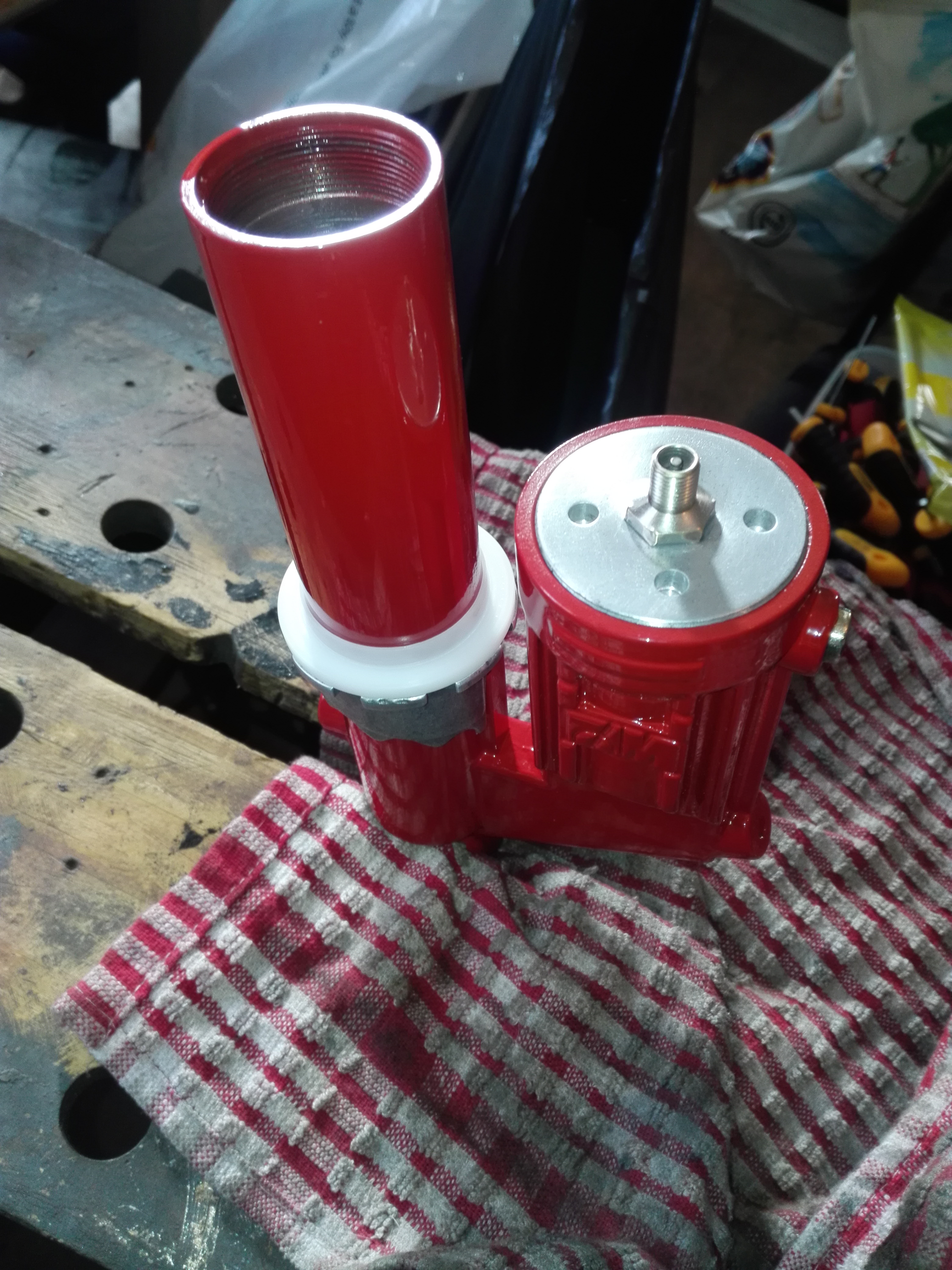
Here is a better picture of the spacer
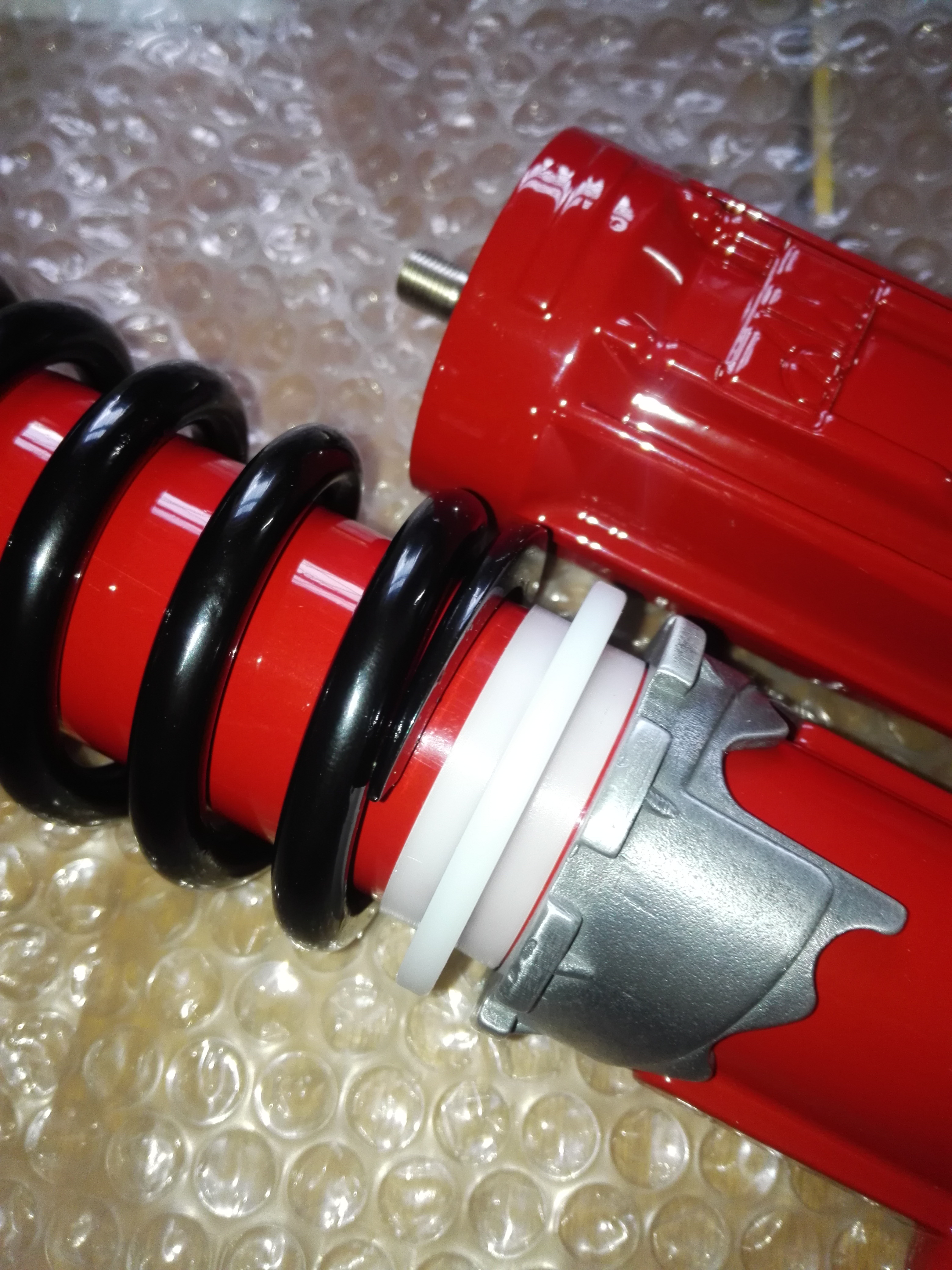
Next the whole thing was reassembled with new oil and the new main seal. Then the spring compressor was used with a bit of masking tape as protection. You can also see the fresh plating on the drain screw.
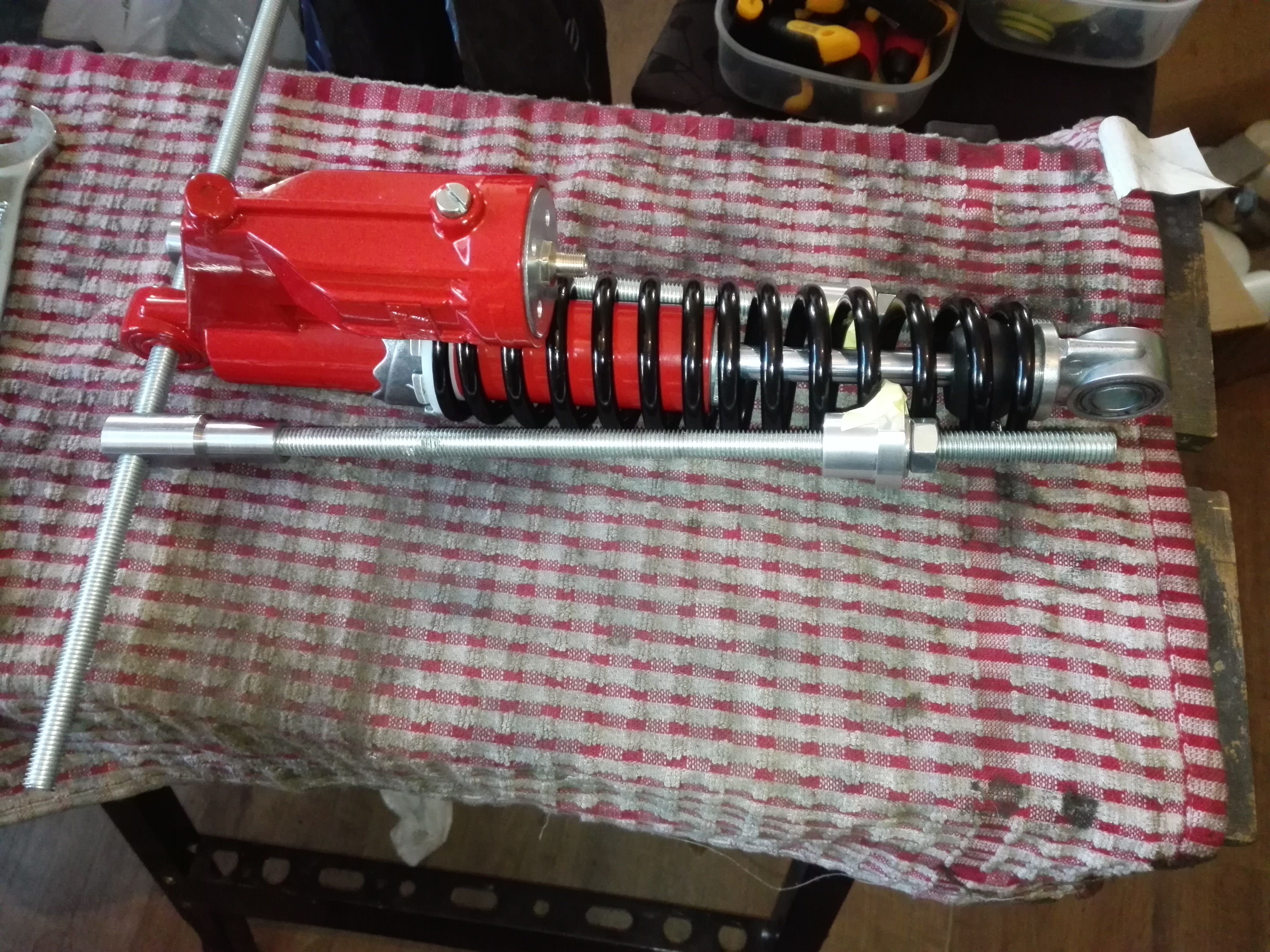
And here is the end result. I’m quite happy with it. I still haven’t decided on a colour for this bike. The V5 says green but it should be red which would match these shocks well 🙂
More to follow
18th November 2018 at 6:25 pm #24417Ownthesky2010ParticipantIts been a couple of busy weeks and I haven’t had a lot of time for this project but I have decided its time for the rest of the bike to get stripped down.
I have taken the wiring harness off to repair it and done a few small bits and pieces but I want to try and start the motor before stripping the bike down so I can get some idea of its condition. If it runs ok with no knocking or smoking then I shouldn’t need to take it apart. I made up some temporary wiring for the ignition system and oil light and put the carbs pack on. I cleaned the points but I didn’t even look at the ignition timing or check carb float heights or balance. Here is a short video of the result.
I am going to take the rest apart now and start prepping the frame for powdercoating.
More to follow.
19th December 2018 at 8:47 pm #24492Ownthesky2010ParticipantBack again after a bit of a break. Work hasn’t stopped but it has slowed down a bit as other priorities take over. Also, I have been working away for a few weeks which makes it difficult to find the time to work on this. I have managed to get a few bits and pieces done.
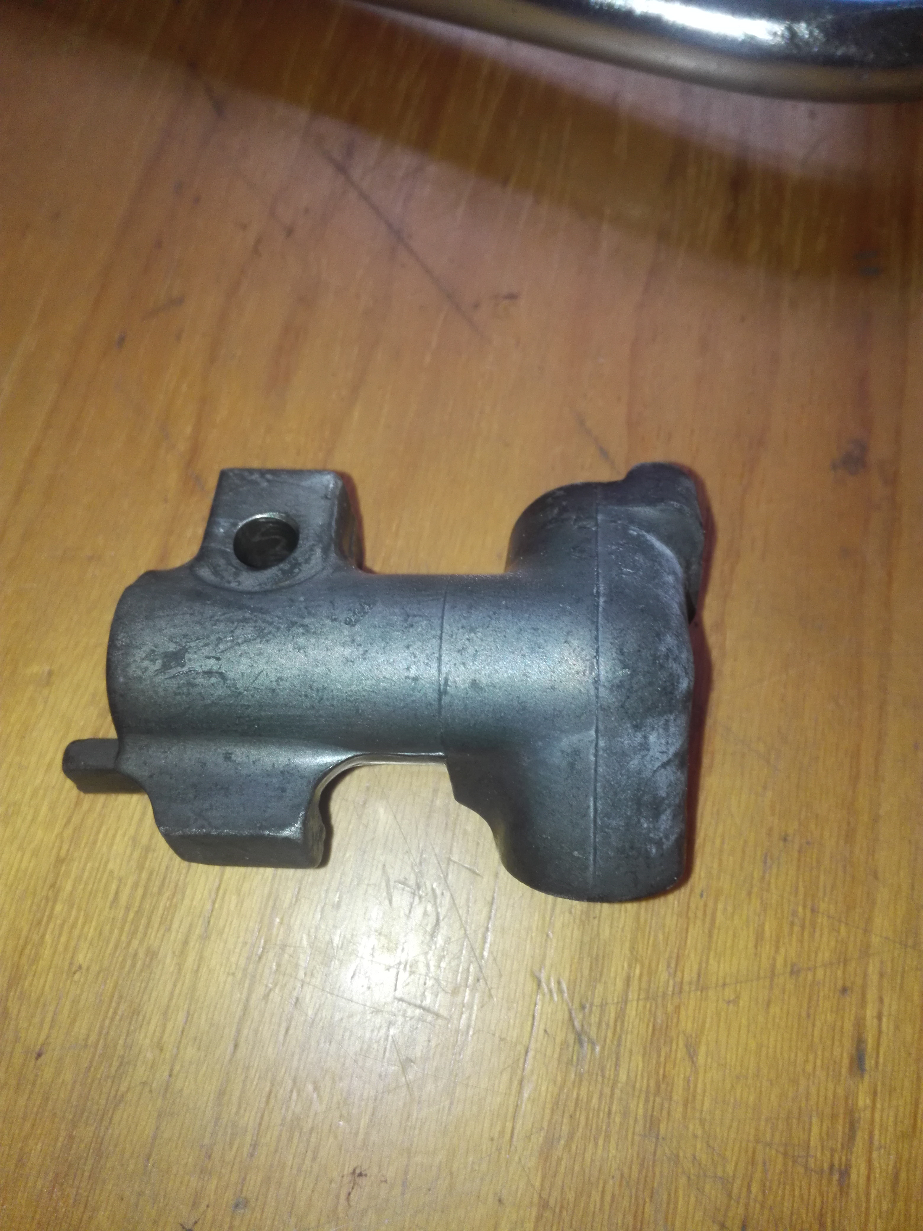
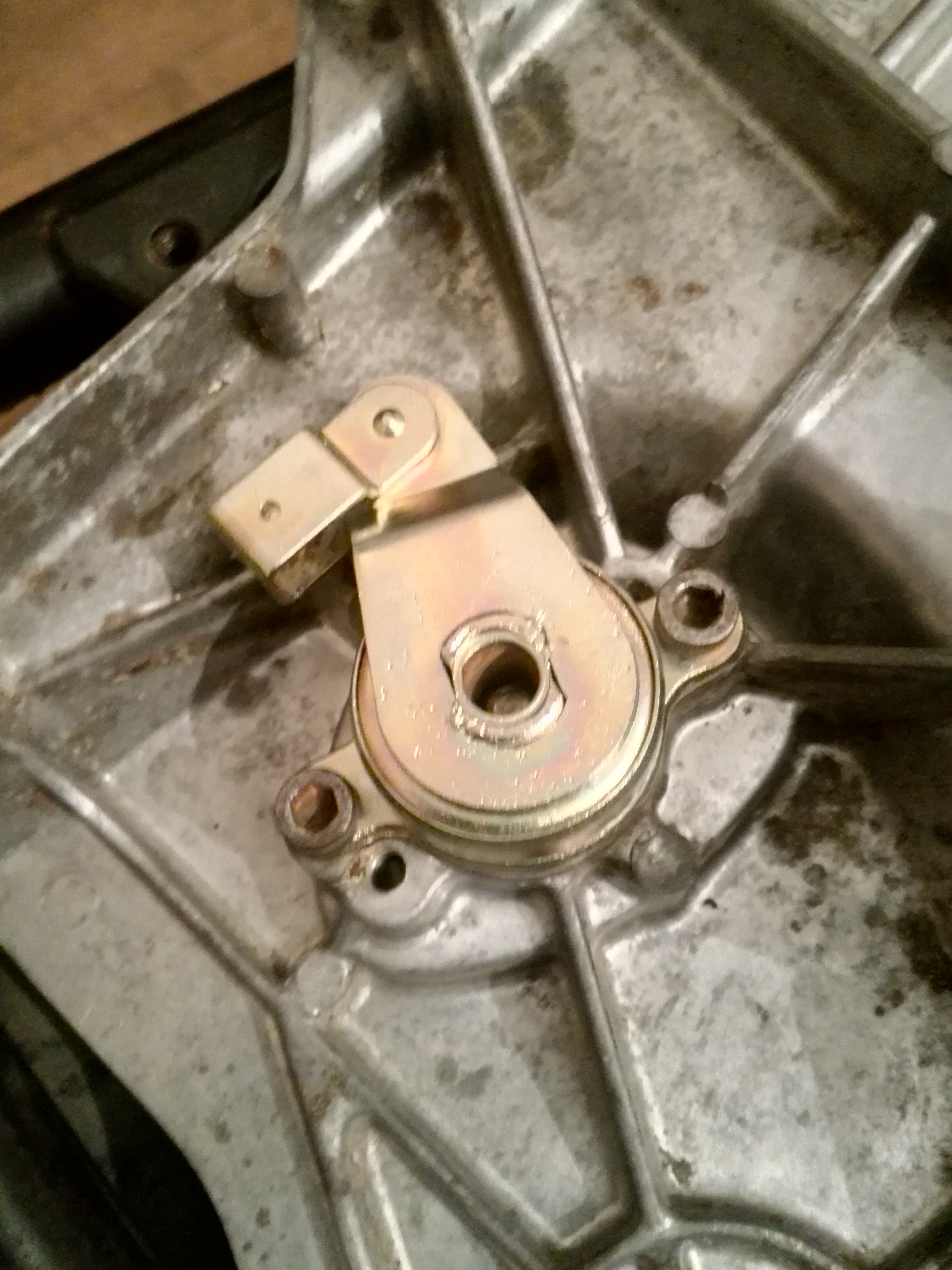
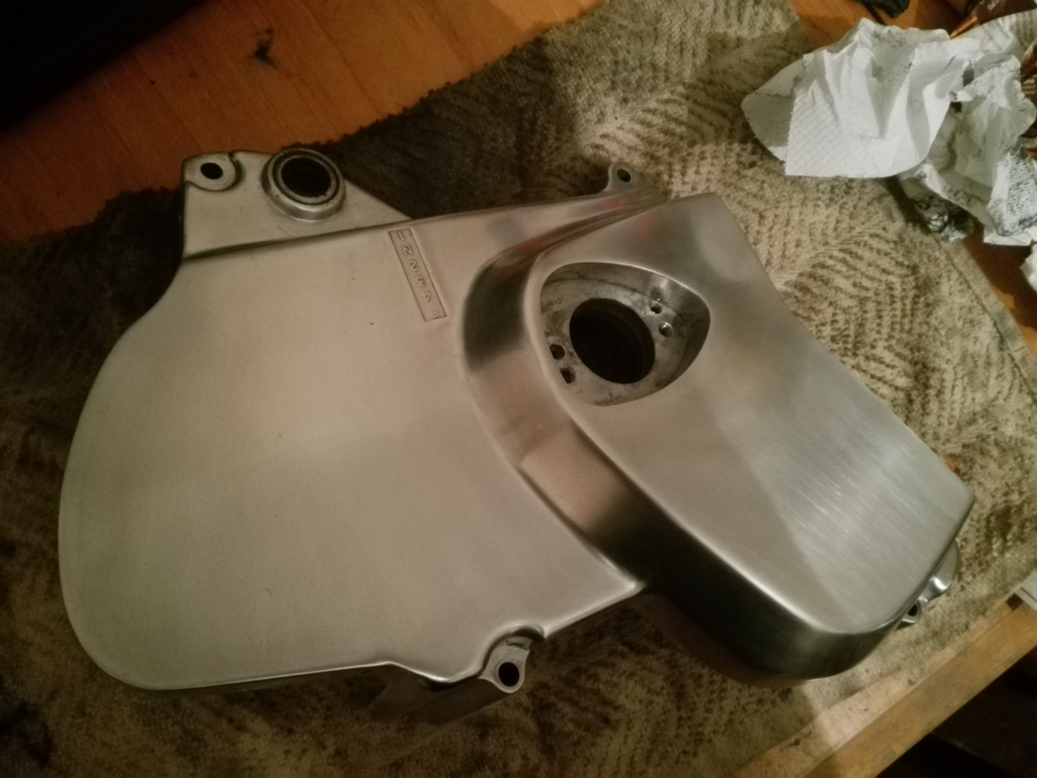
While I had the sprocket cover in my hand I decided to sort a few bits out so it got a good clean in solvent.

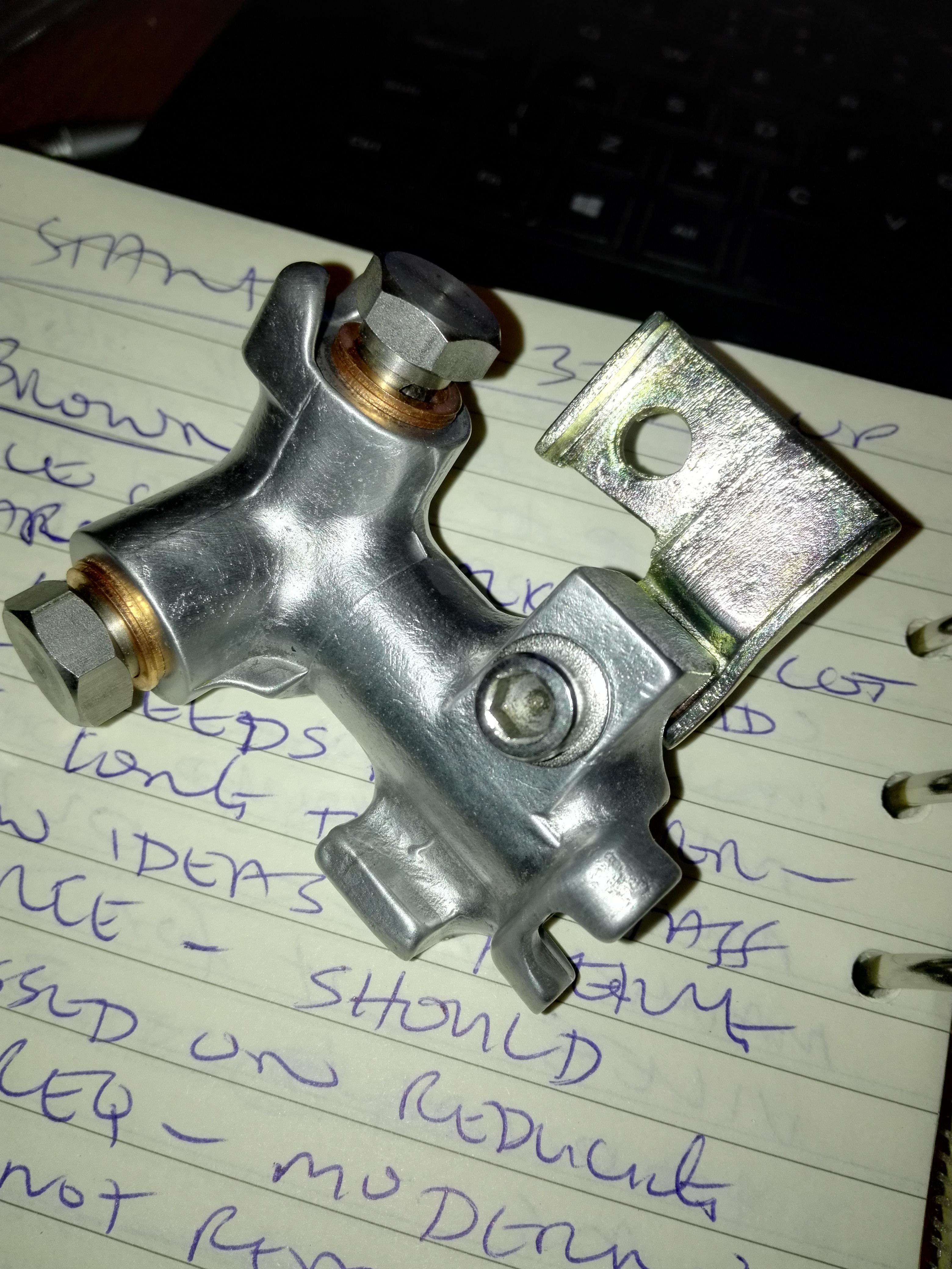
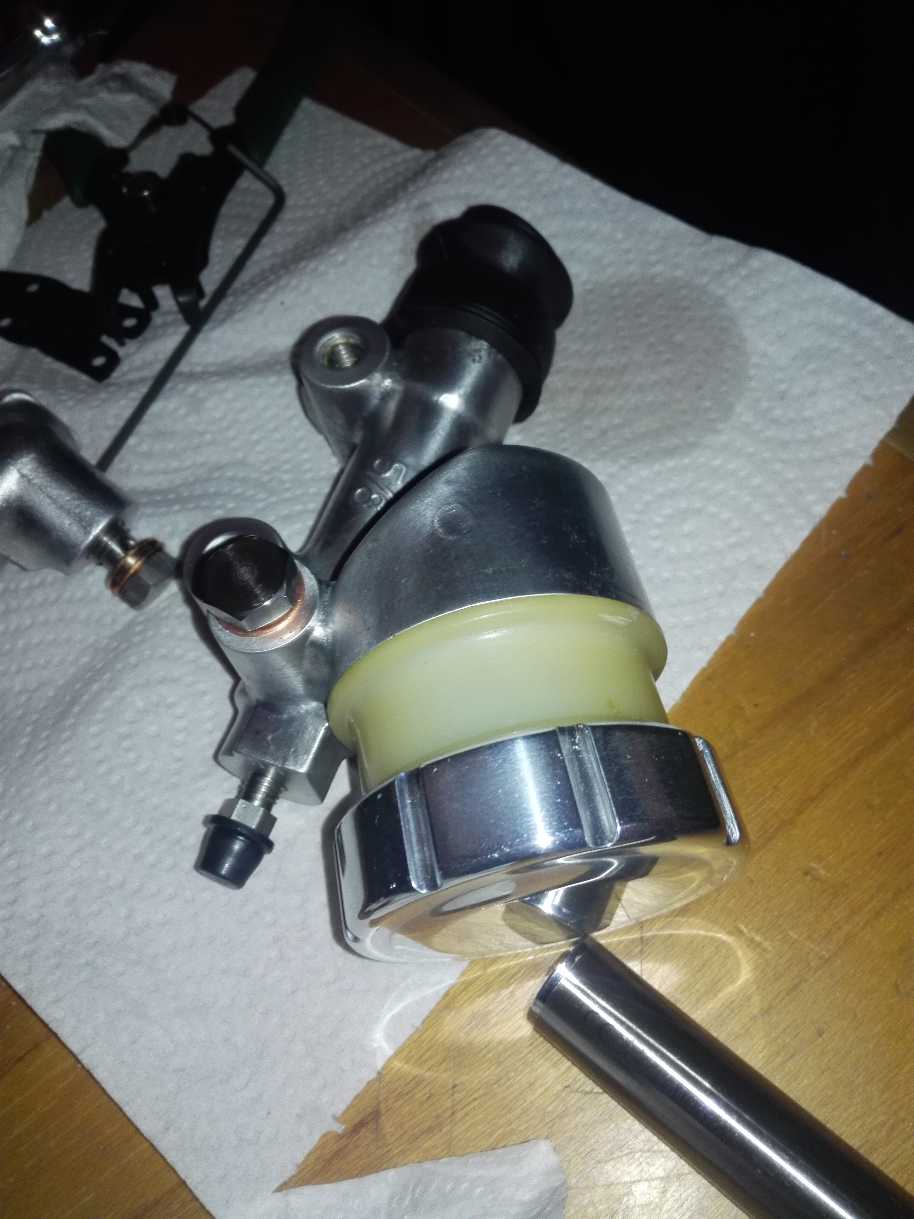
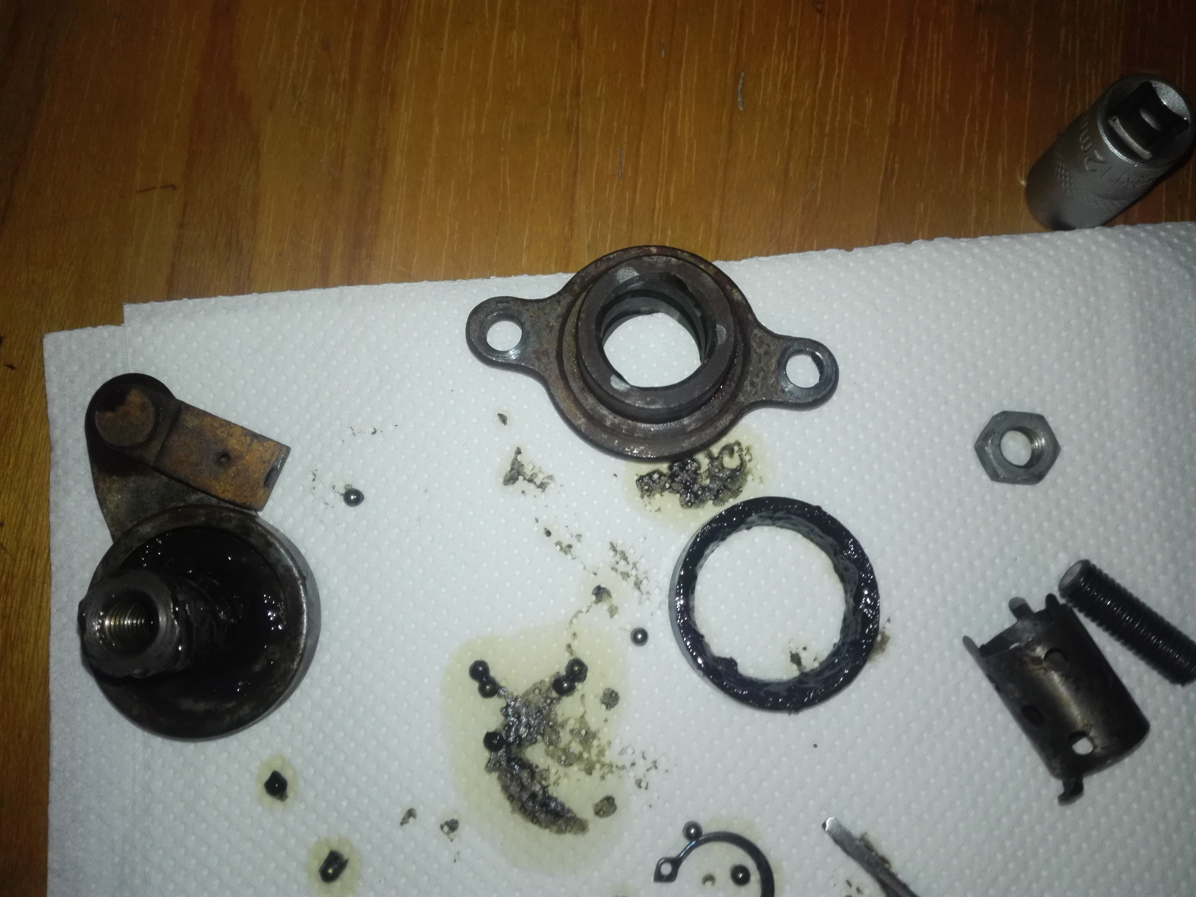
I stripped the clutch actuator and plated the parts and then reassembled with new grease. The balls and seal looked ok. There is a bit of wear to the screw but its smooth enough.
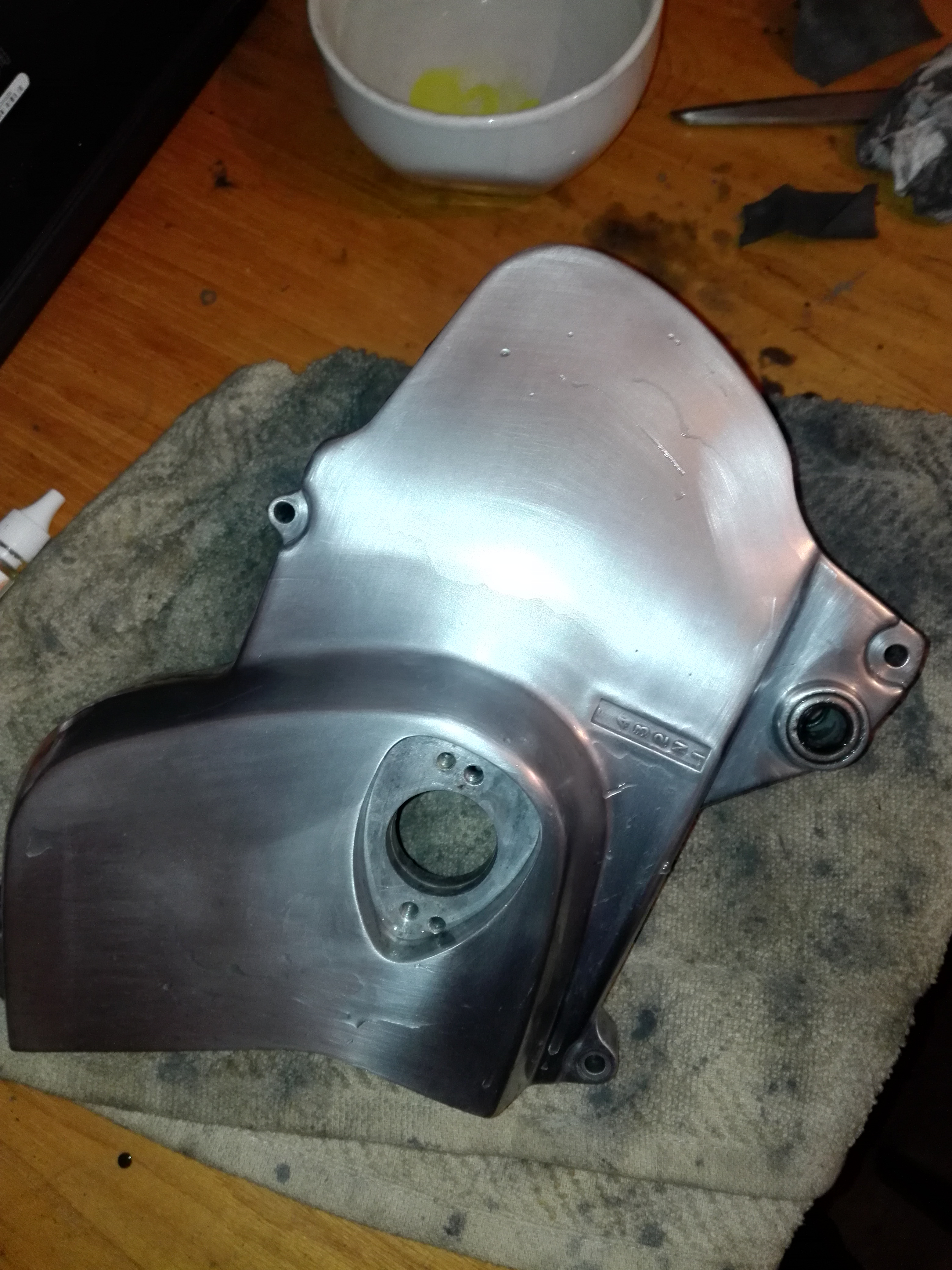
I took a file and some sandpaper to the outside but I wont polish it until later. It should come up nice and shiny.
 19th December 2018 at 9:03 pm #24508Ownthesky2010Participant
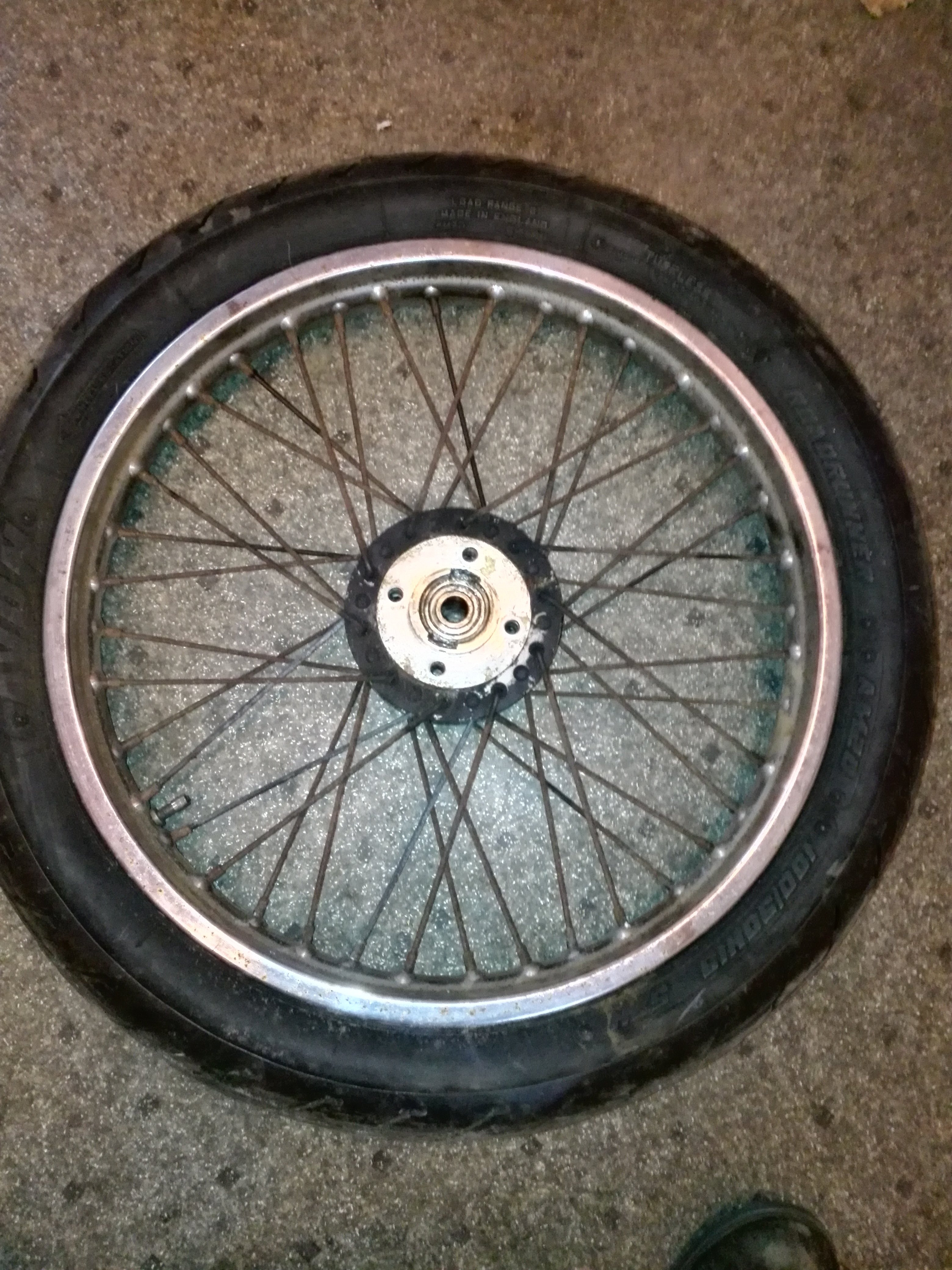
Next up I started on the front wheel. As with everything on this bike it was covered in a thick patina. Many of the parts have been preserved by this but unfortunately the wheels both have a lot of corrosion. The rims are probably dead but I might be able to re-use the spokes.
First off the disc is removed
Next the tire comes off, an absolute pig of a job.
I tried cleaning the rim a bit and its definitely too far gone. The corrosion is worse on the inside.
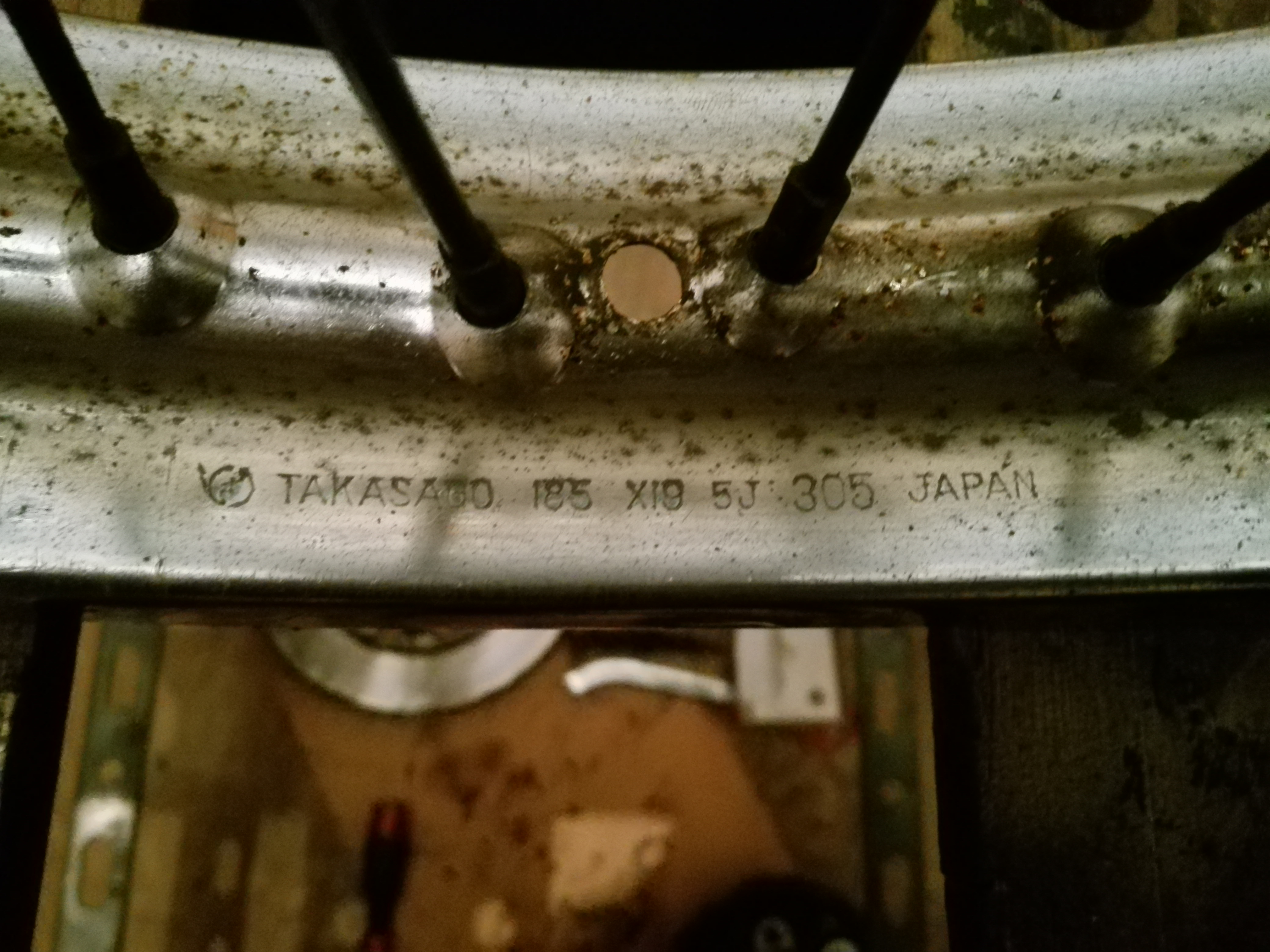
Don’t forget to take some measurements before stripping the rim.
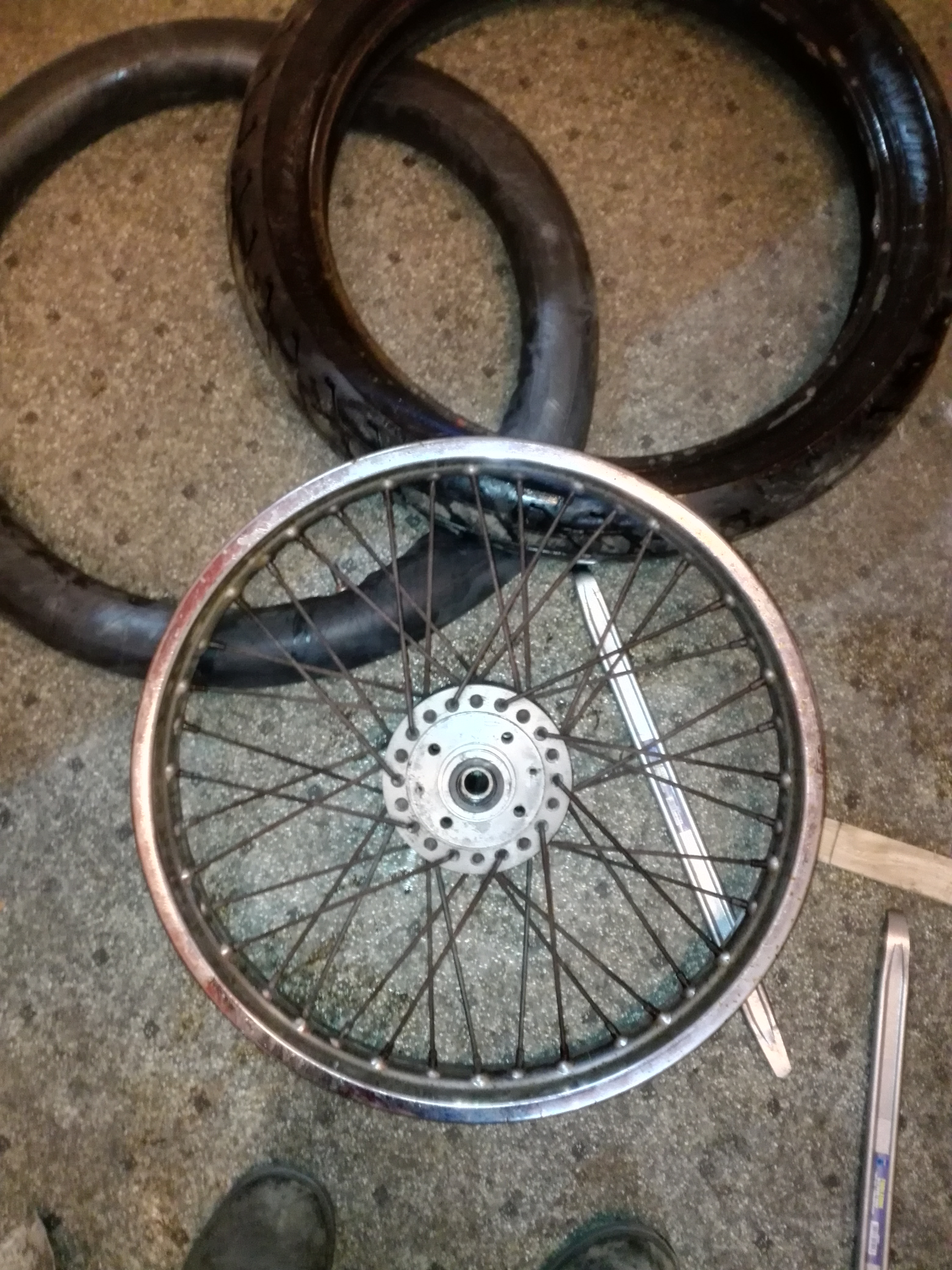
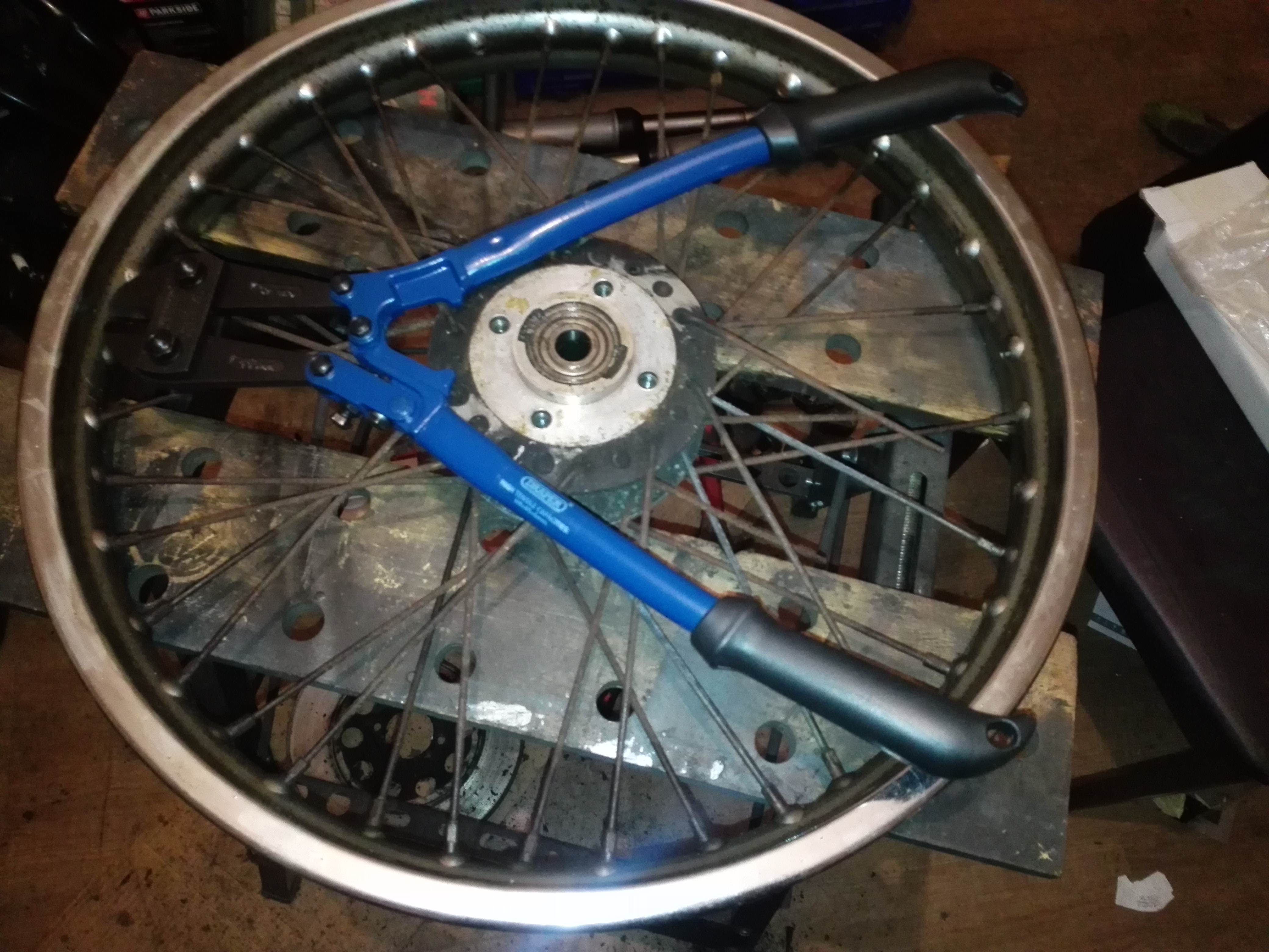
I did my best to unscrew the spokes but they were all seized solid so I ended up buying a pair of bolt cutters to remove them. Pity as it can cost up to £80 for a set of spokes.
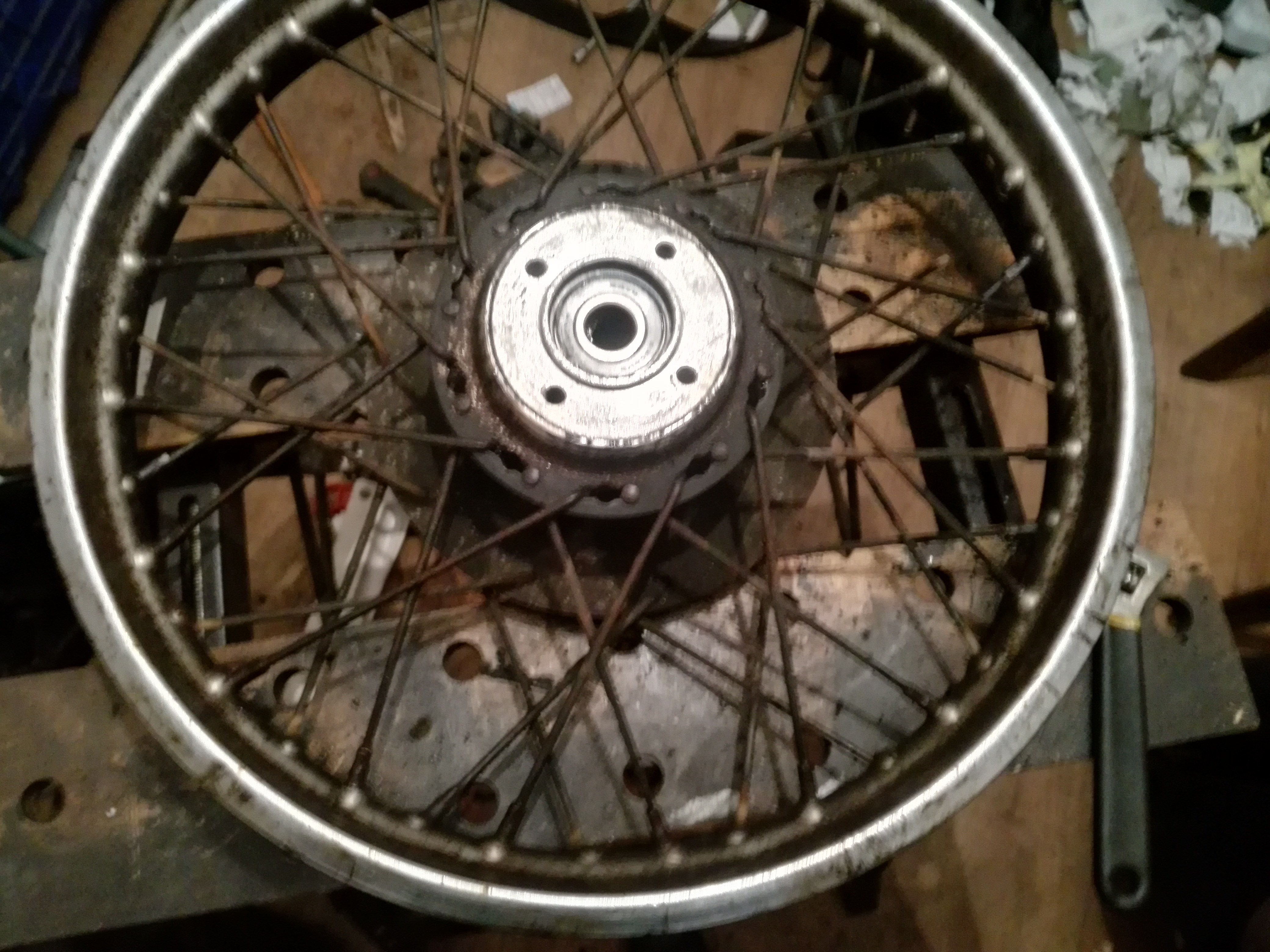
Here is the hub after cutting the spokes.
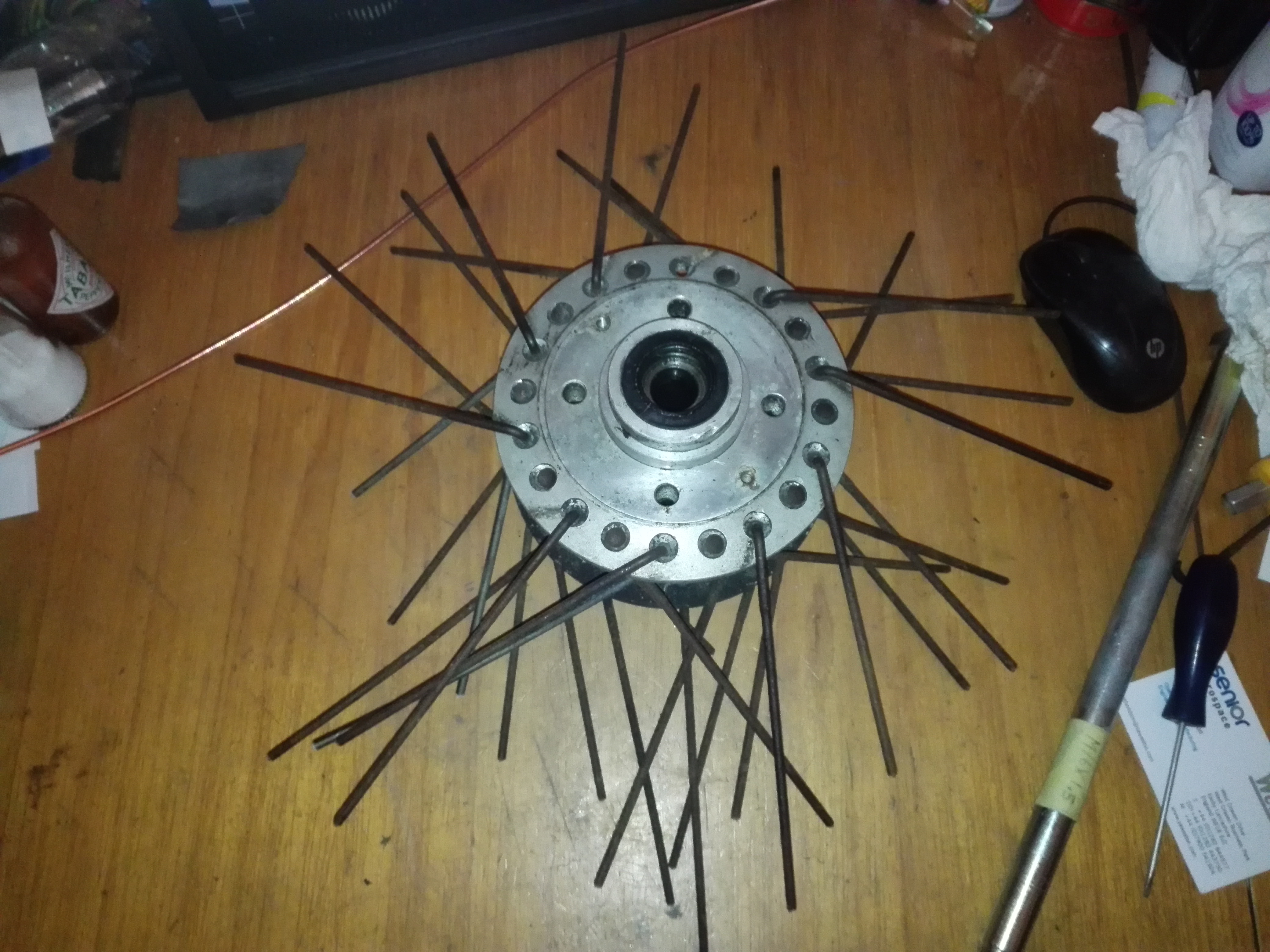
I attacked it with a wire brush and scotchbrite wheel but there is no way I will get it clean enough like that so I’m going to sandblast it and then paint it silver. It will look pretty good with new spokes and a new rim. I also plated the axle bolt and spacers while I was at it and then did the rear axle bolt and swingarm bolt too. I cant fit the long bolts in the plating tank so I just plate the ends as can be seen in this photo. This plating kit is coming in very handy.
 19th December 2018 at 9:17 pm #24509Ownthesky2010Participant
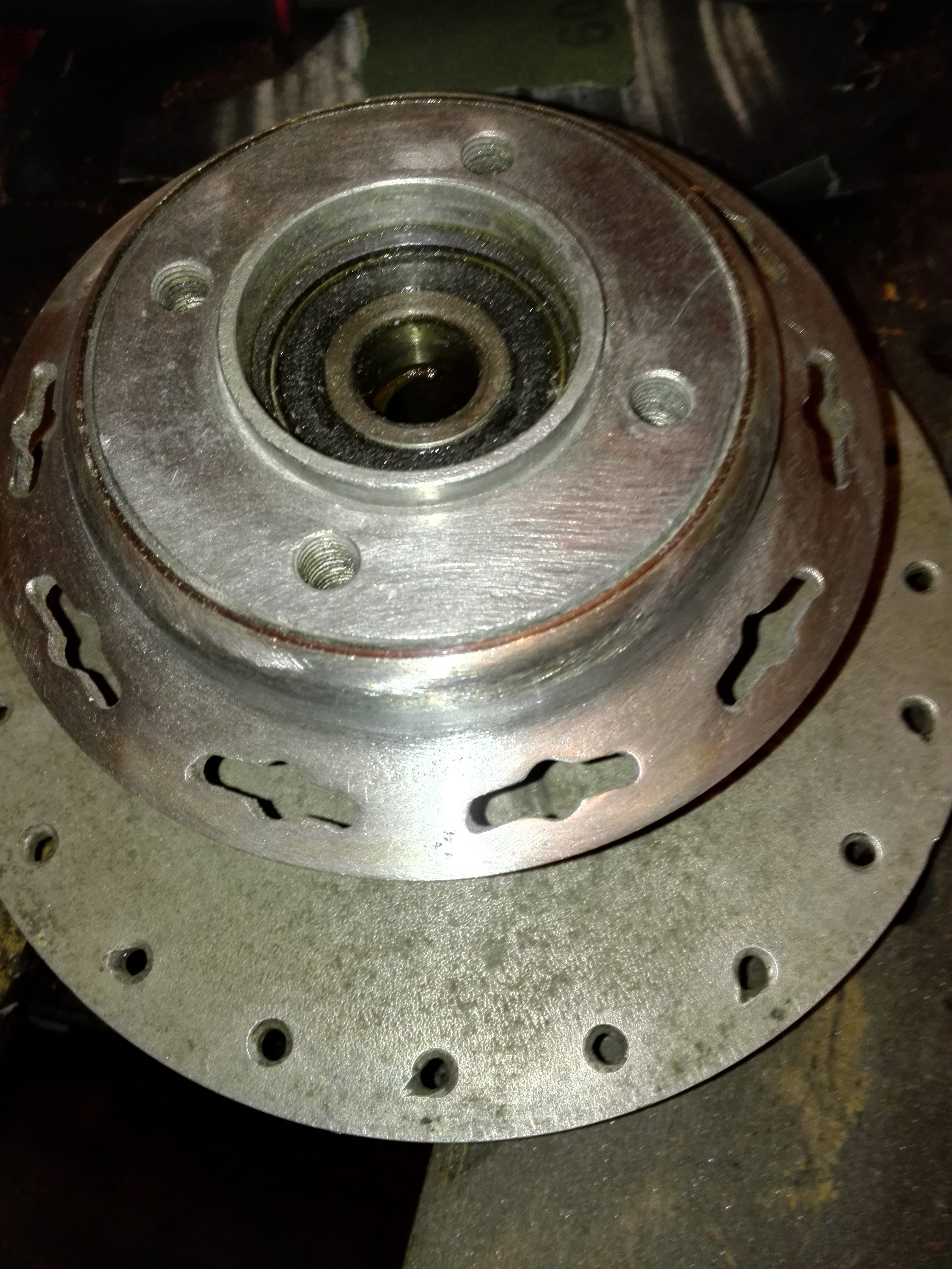
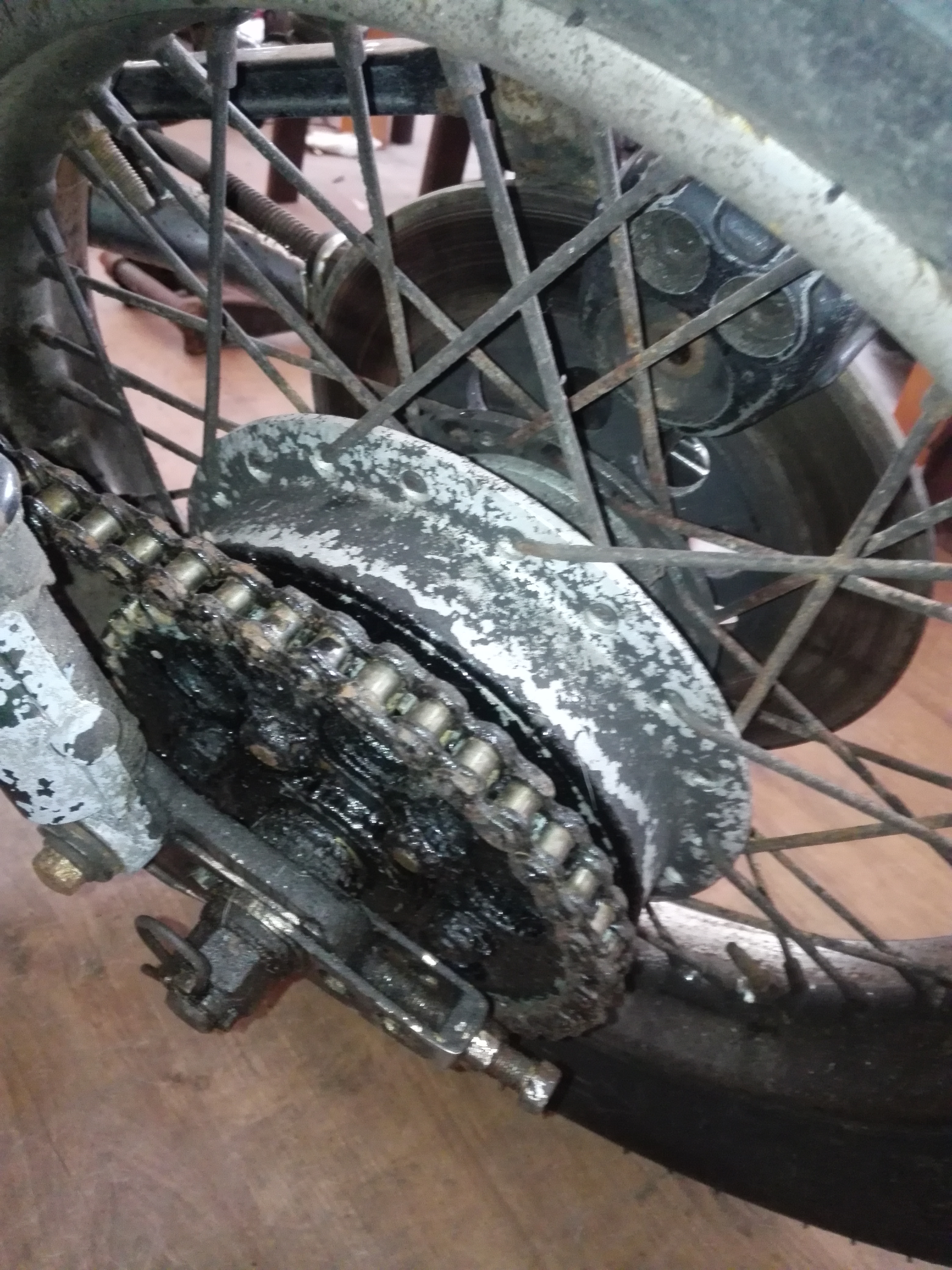
Next the rear wheel gets the same treatment. I managed to remove almost all the spokes but I still broke 2 of them. I have resigned myself to replacing them all now. The rear rim is also completely shot and will be replaced.
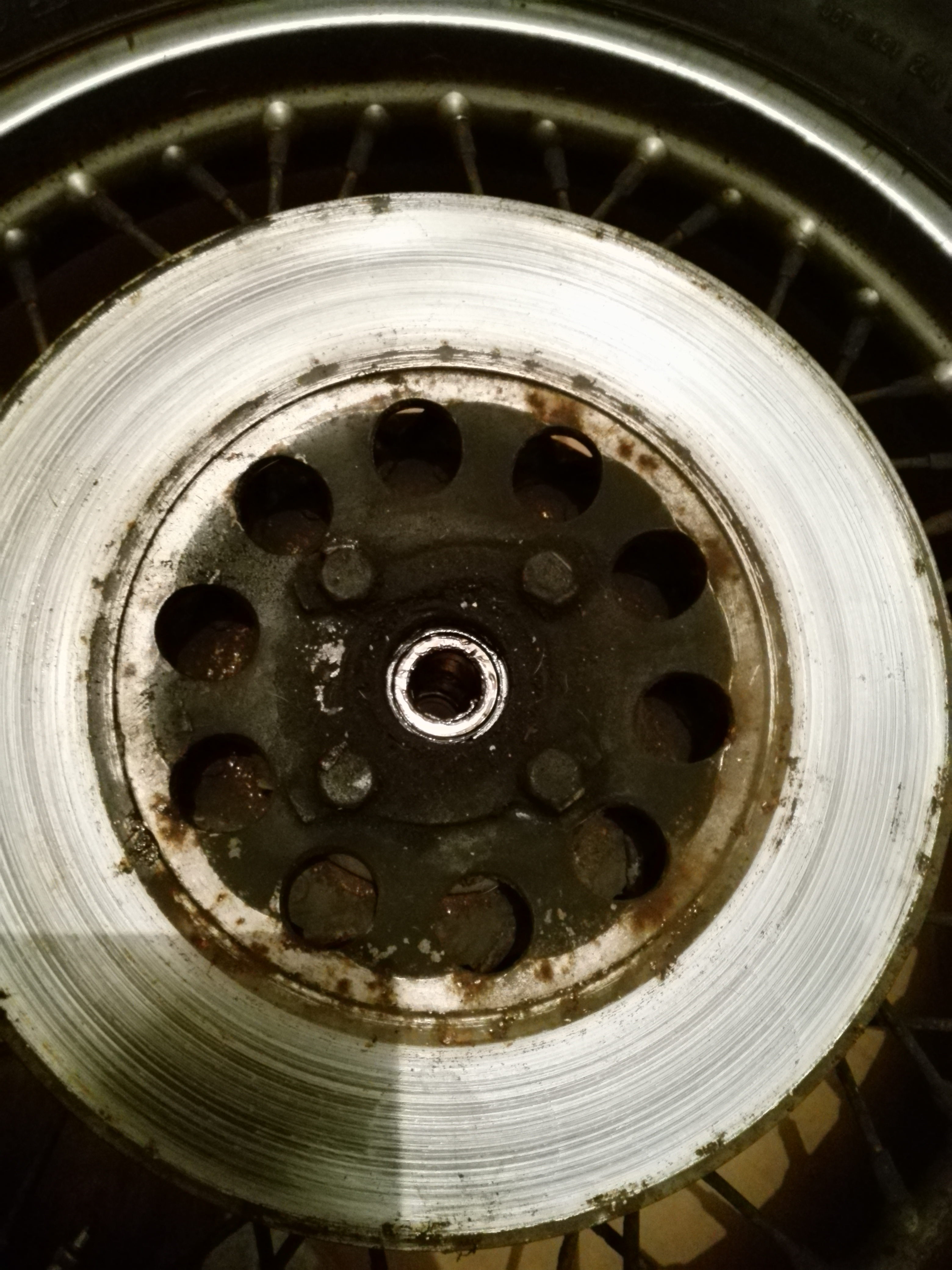
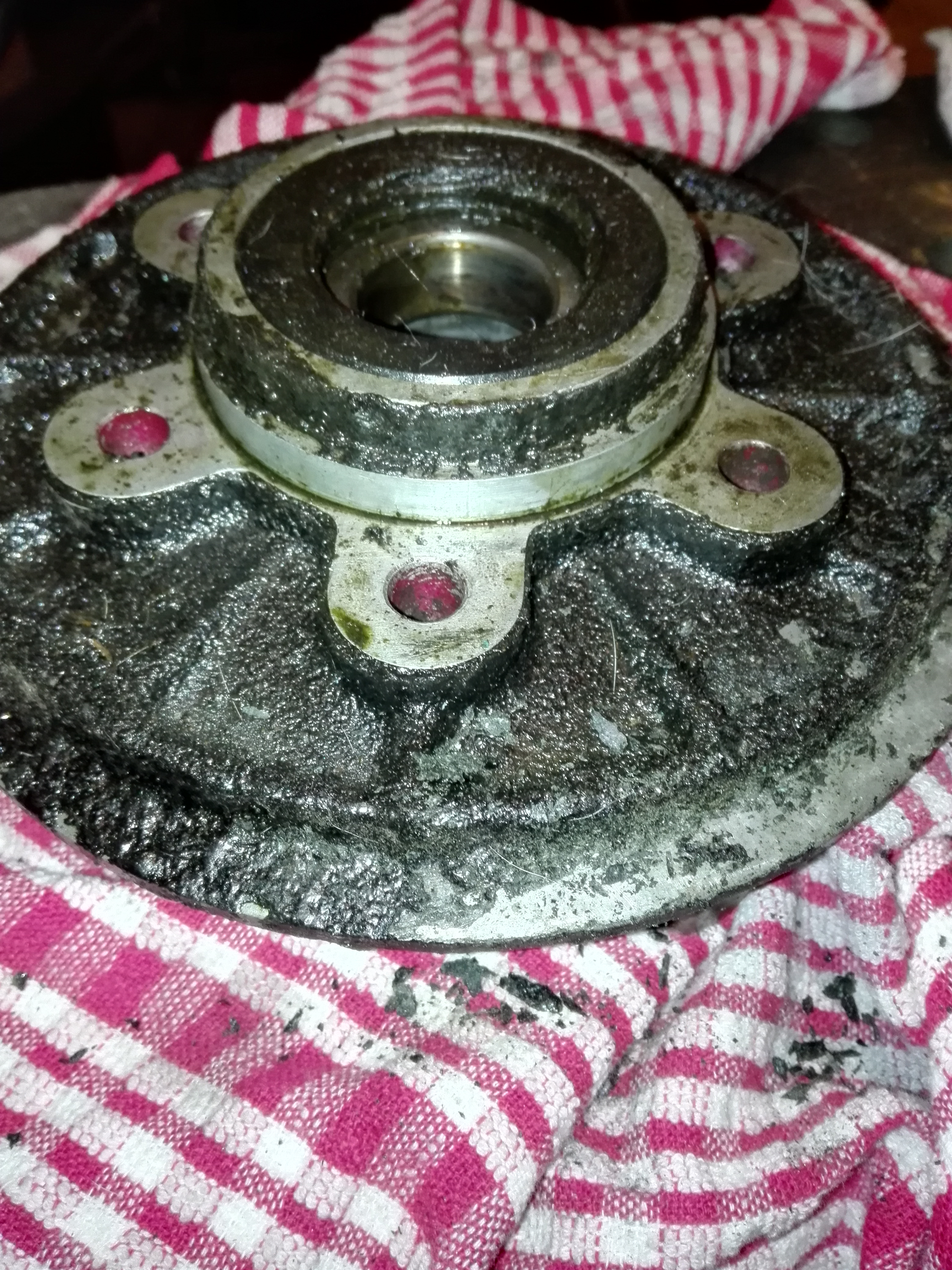
Once the spokes were removed and the hub could be inspected I found a problem. The sprocket side of the hub is cast aluminium but the disc side has an outer ring of steel that’s chrome plated. This is going to be a bugger to repair.
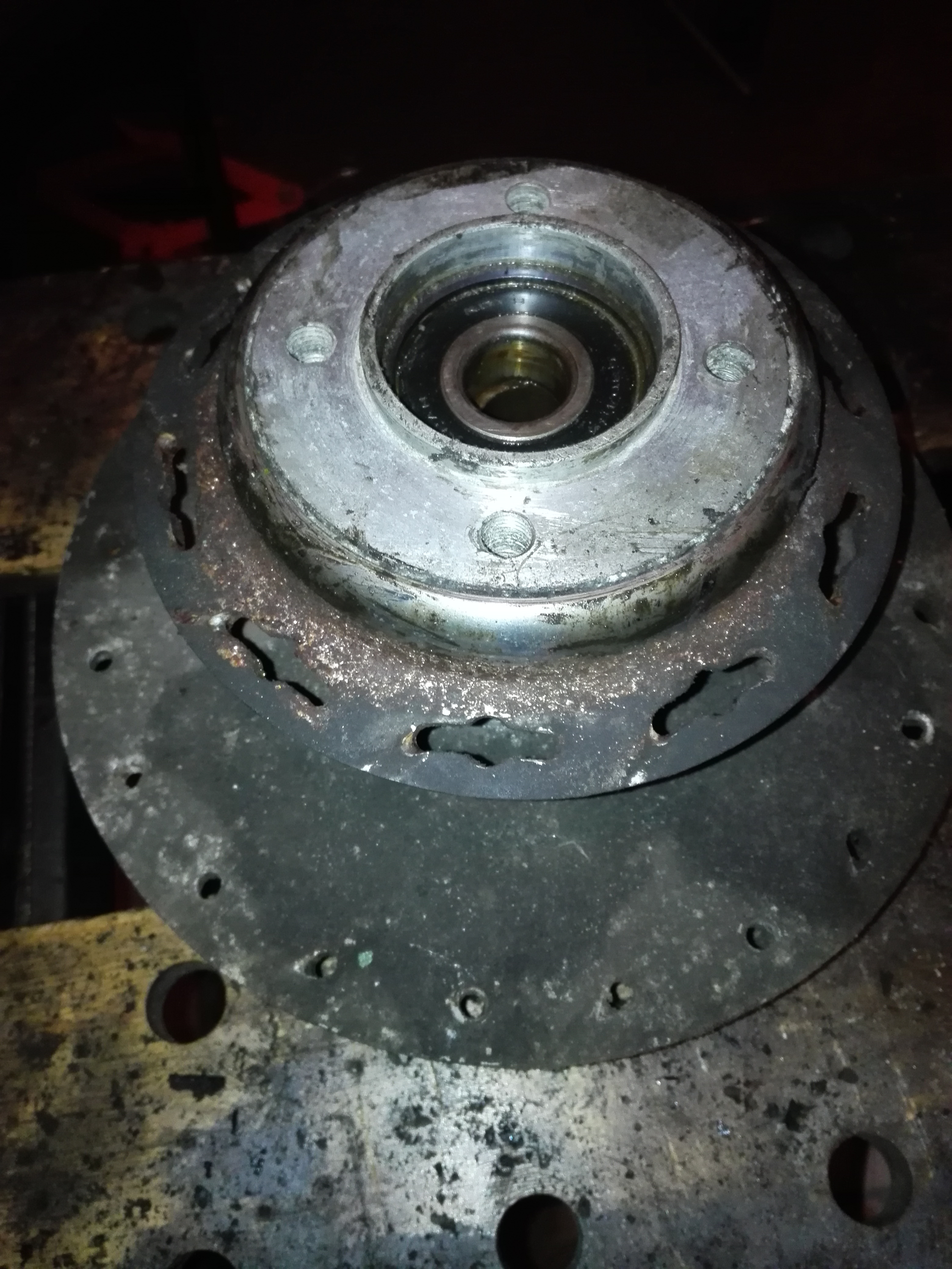
After a bit of cleaning its clear the chrome on the ring is bad. I’m going to have to strip the chrome off to paint this. I’m not sure how yet but tried a few ideas. Its obviously going to he much harder to sort out on the inside but that’s something to worry about later.
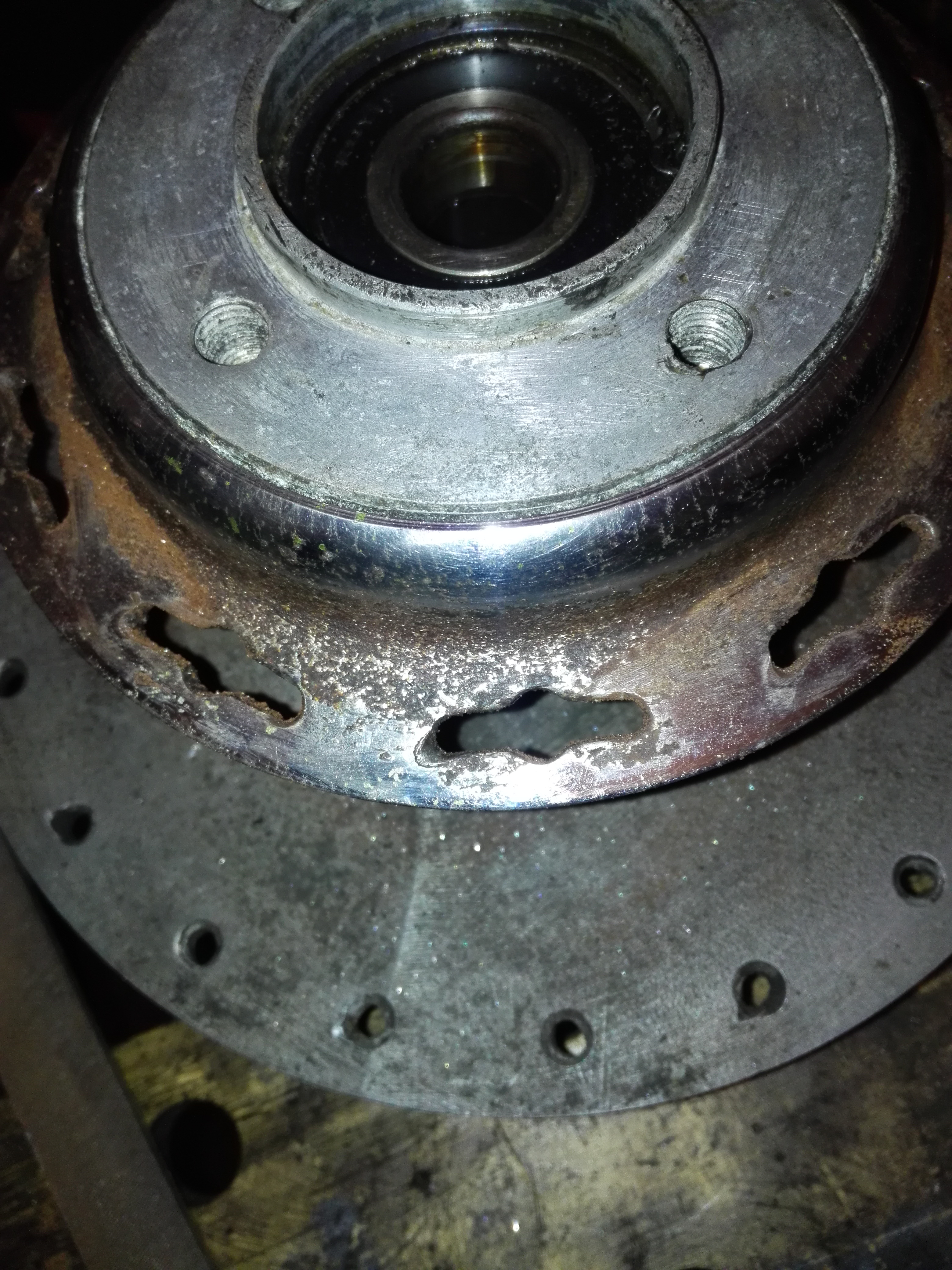
First I tried a bit of sanding with coarse paper to remove the flakes

Then a stainless steel rotary wire brush to dig out the rust. This left deep craters.
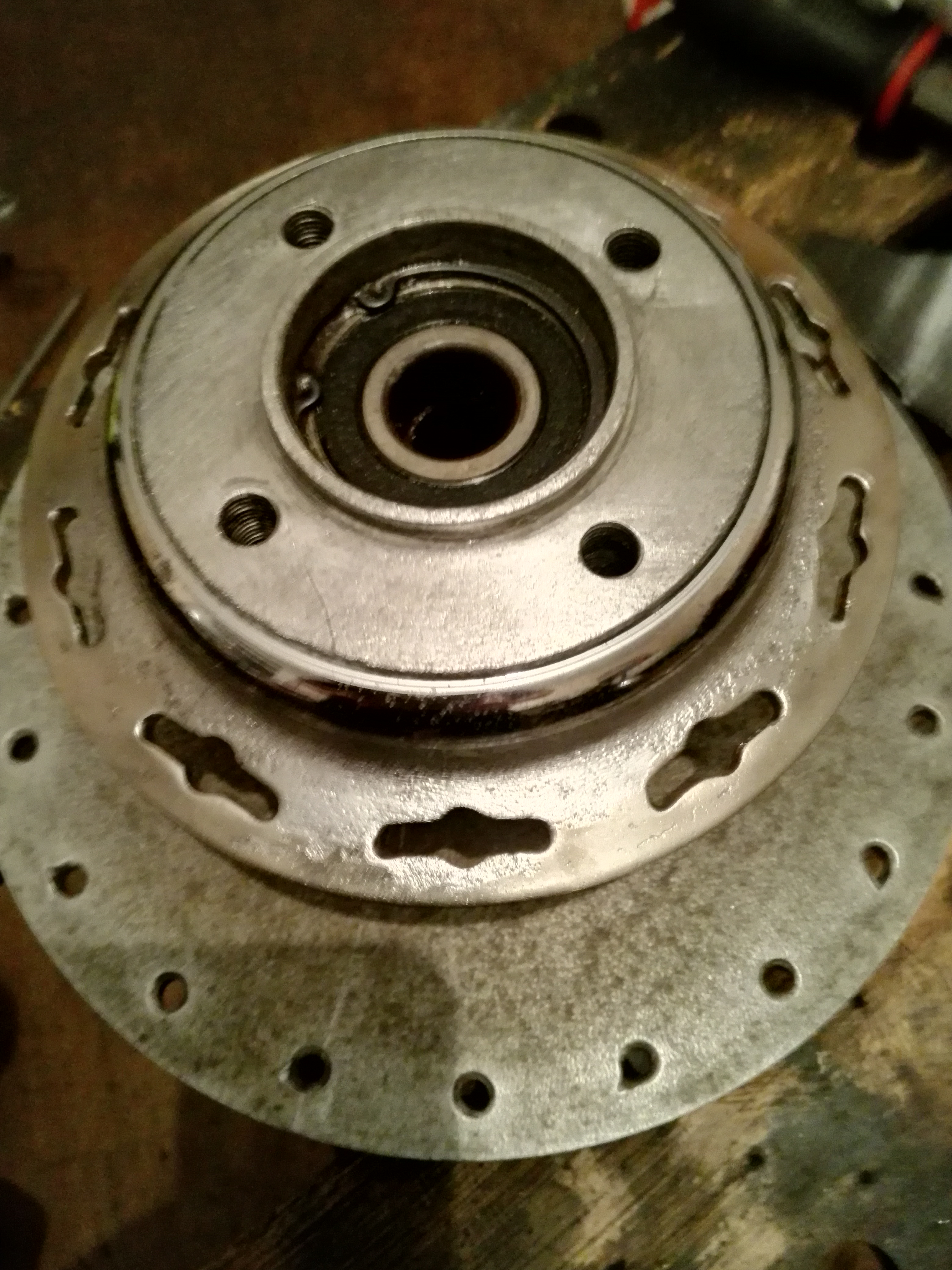
Then a flapwheel on a drill to smooth it all out. Not bad. There is still a bit of nickel left on it but most is down to the steel. I will try something similar on the inside and then the whole thing will be sandblasted before painting along with the front hub. I haven’t ordered the rims yet so there is no rush.
 19th December 2018 at 9:43 pm #24512Ownthesky2010Participant
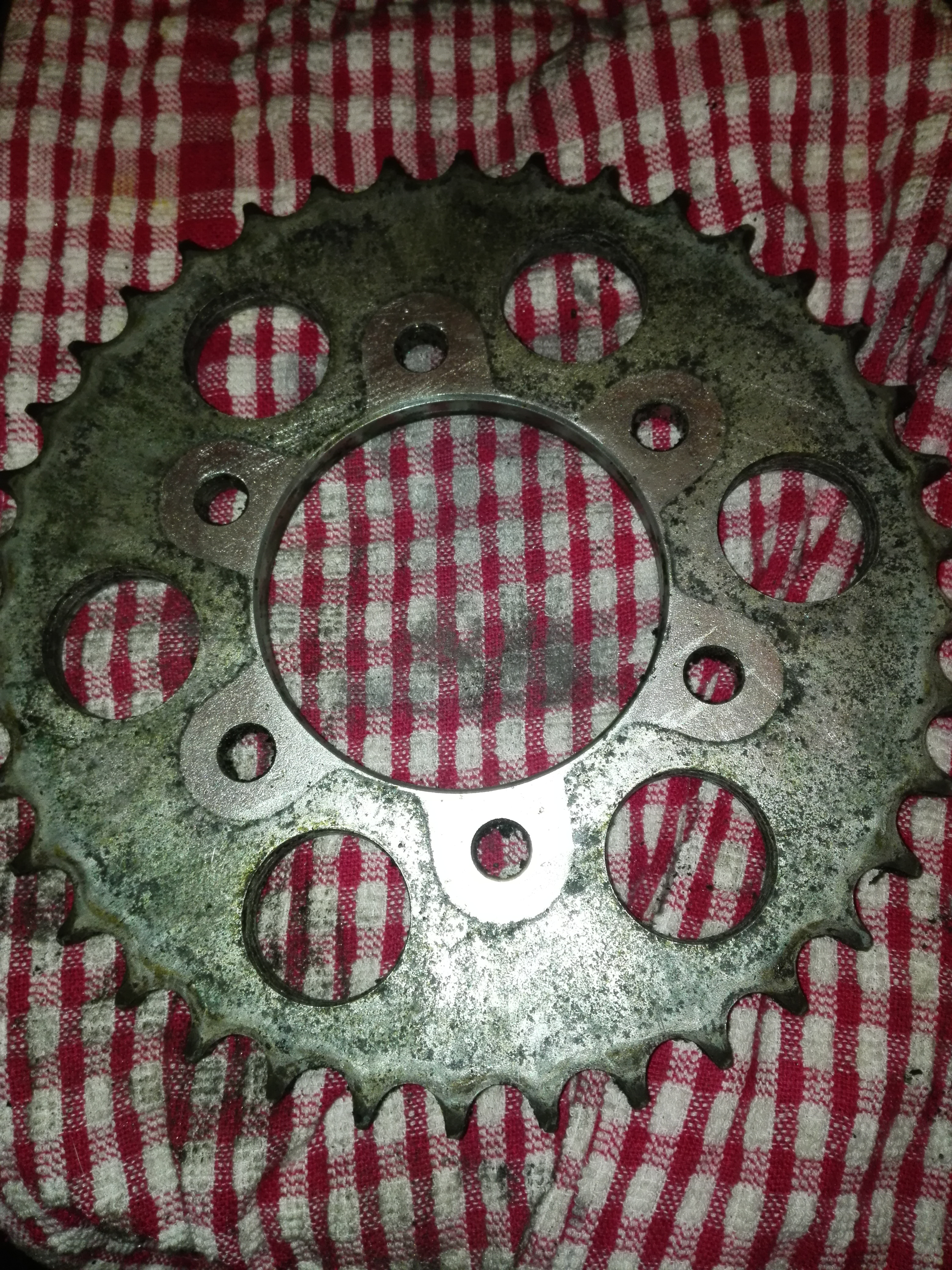
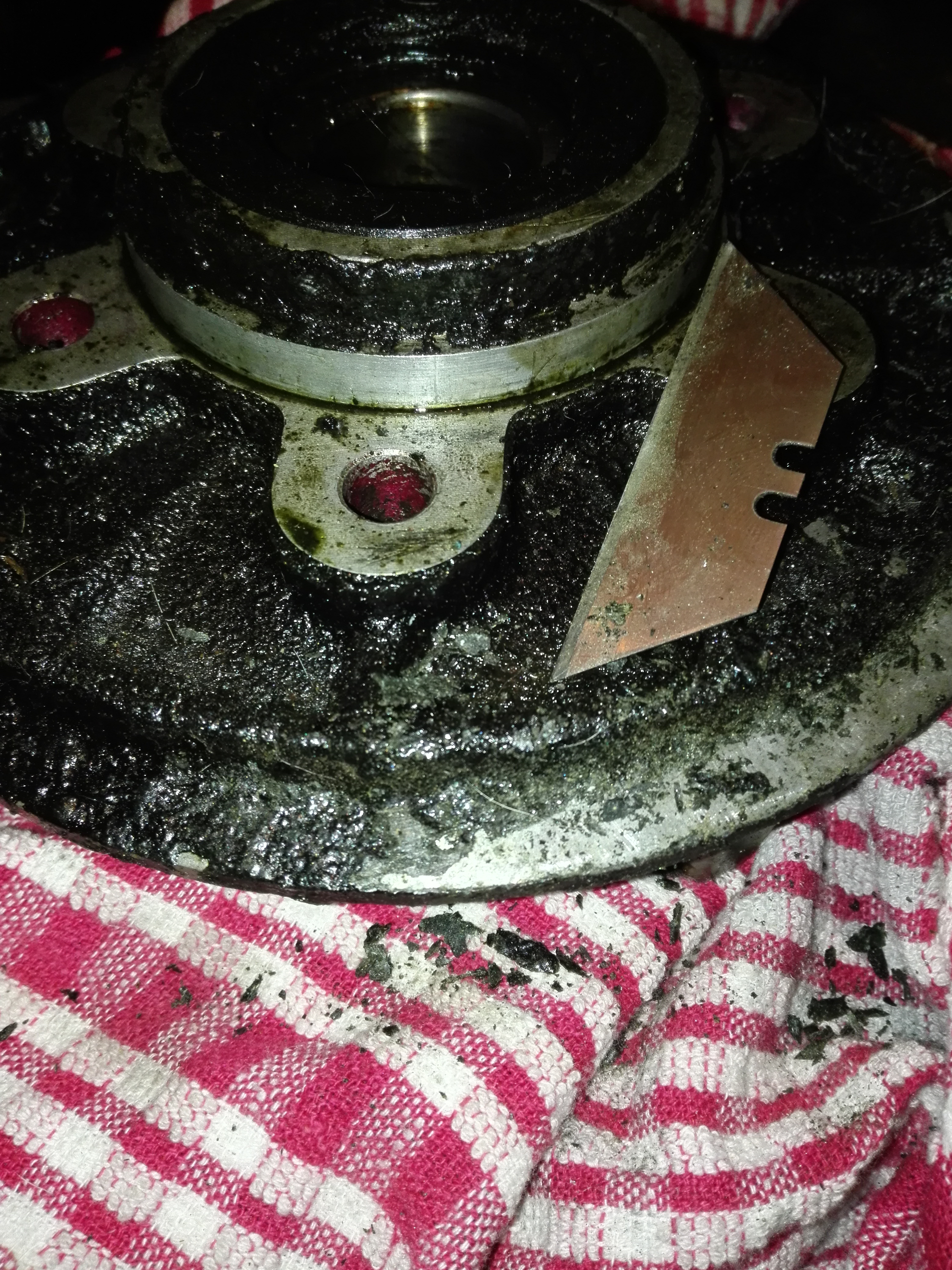
Next up is the sprocket and carrier.
The sprocket looked like it would still be ok but would need a lot of cleaning. There was a lot of rock-hard chain lube on everything. This stuff had to be chipped off with a blade.
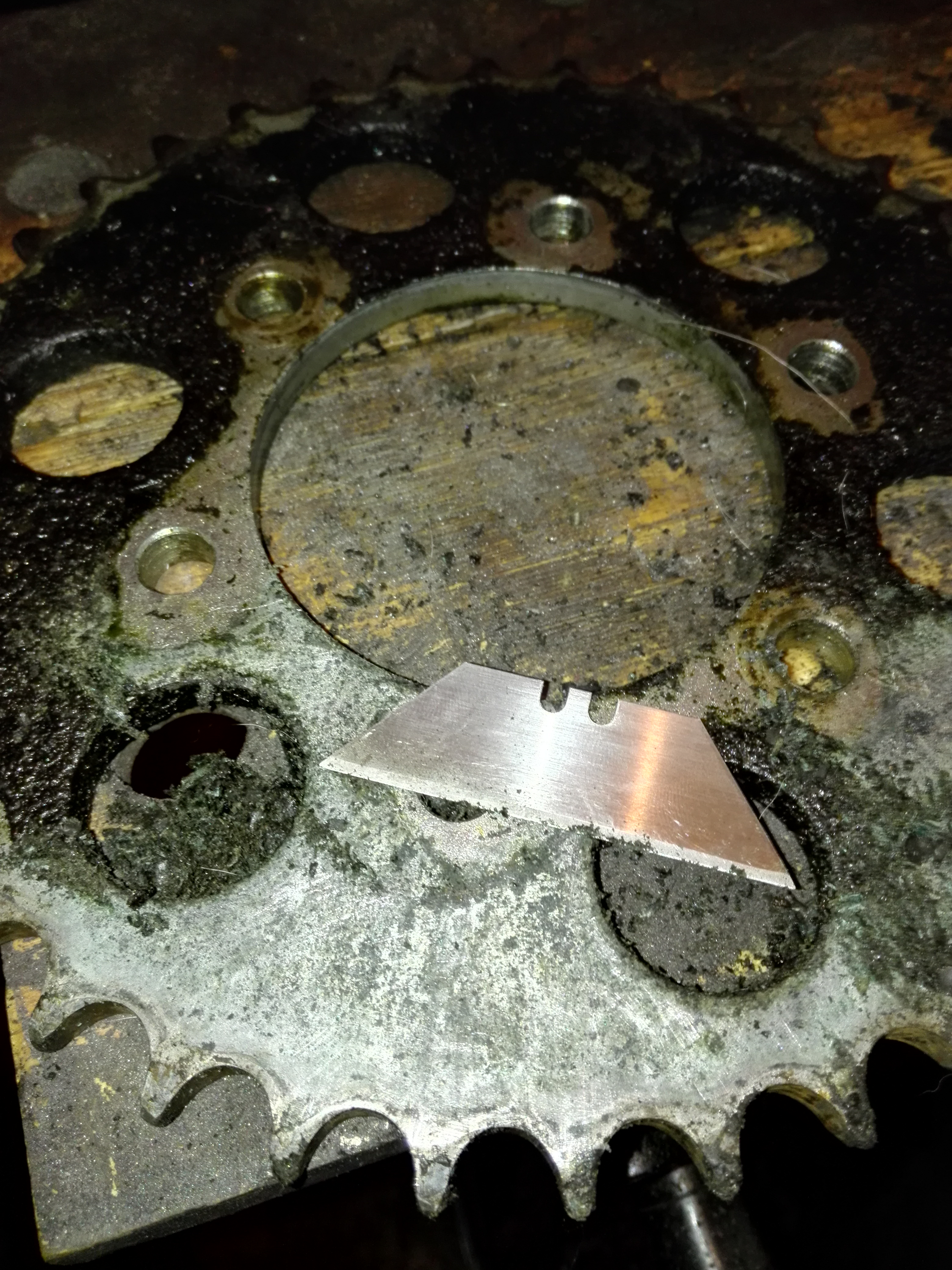
Its really thick
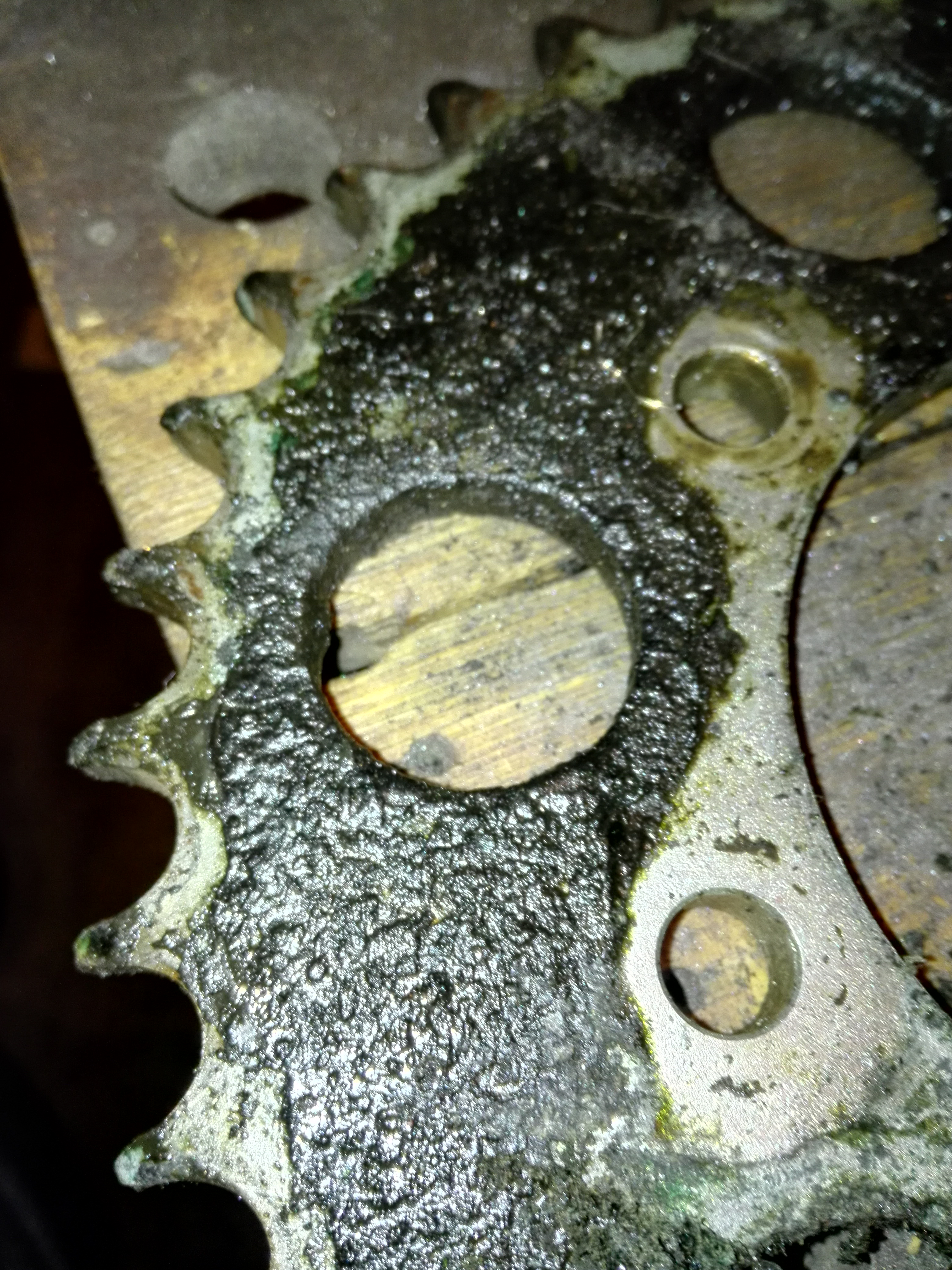
Lots of chipping later and its ready for wire brushing
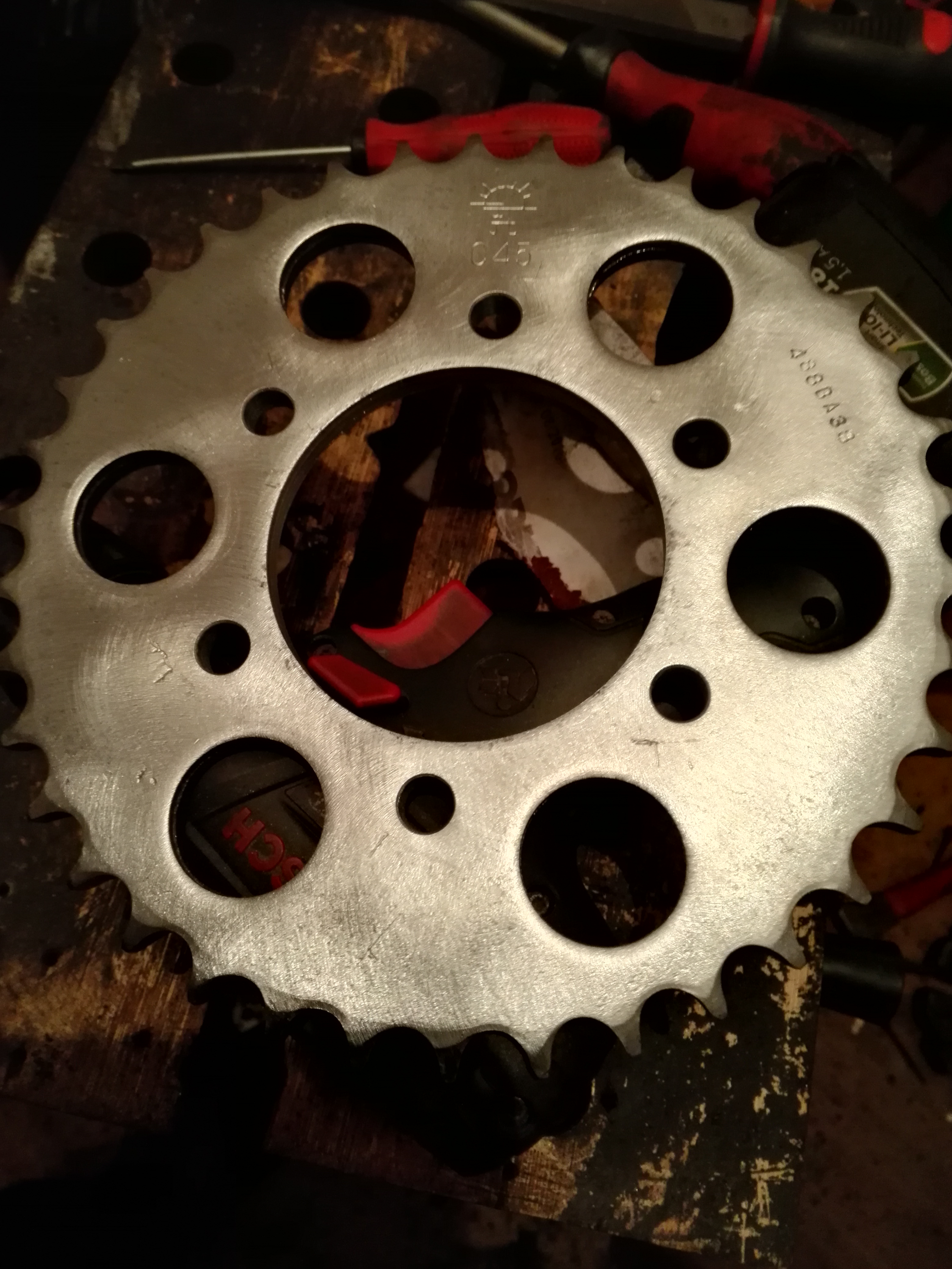
I started the wire brushing on the teeth to check the condition. Hardly worn at all. This sprocket should still be good.

After a lot of wire brushing its all clean. I had planned to plate it but it wont fit in the tank so I will paint it instead.
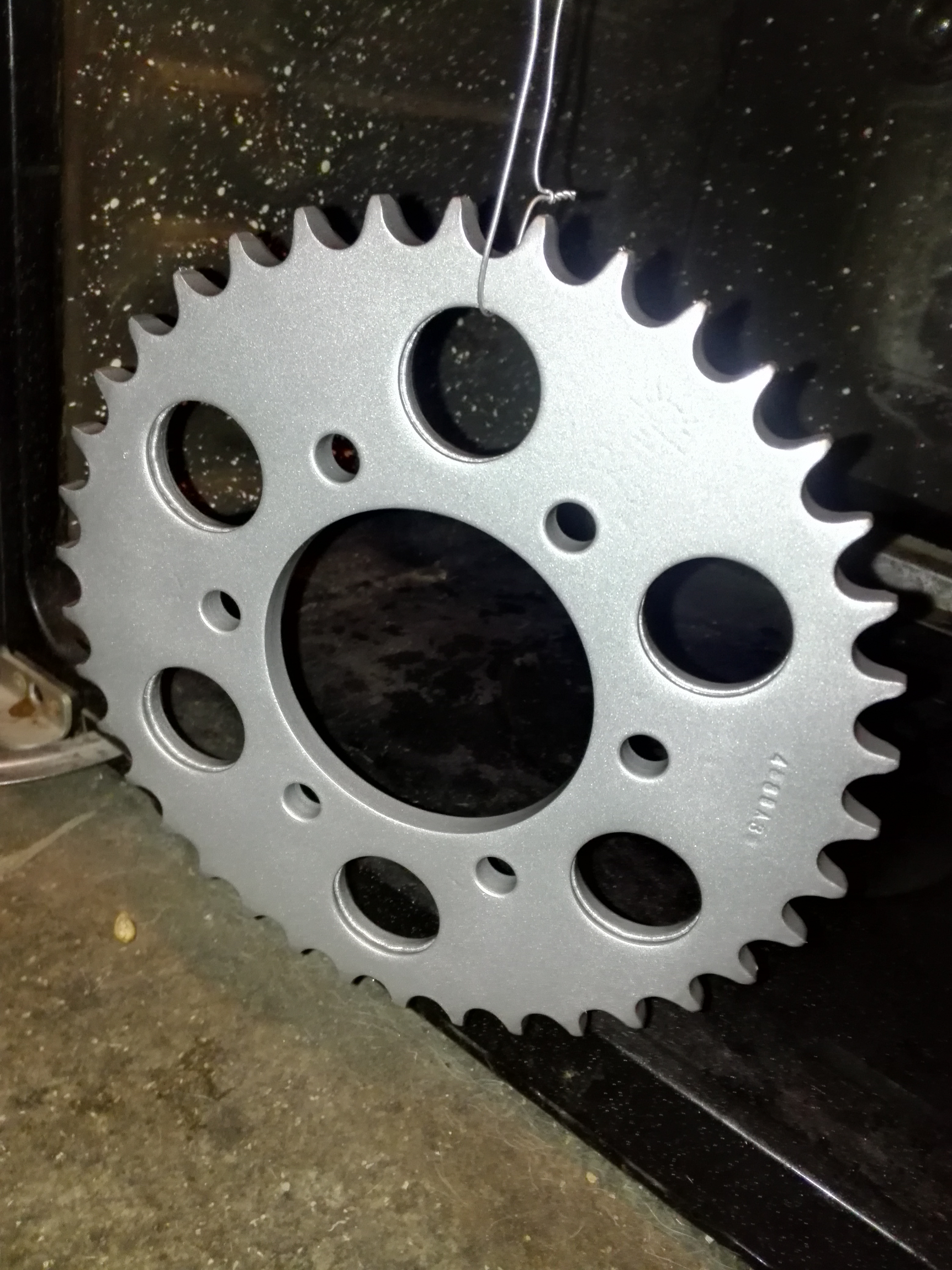
All painted, fresh from the oven and looking spiffy 🙂
Now to tackle the sprocket carrier.
I treated it to the same scraping and chipping as the sprocket.
That’s the easy part done. The only way I could shift the stuff in all the recesses was with a small screwdriver and a lot of patience.
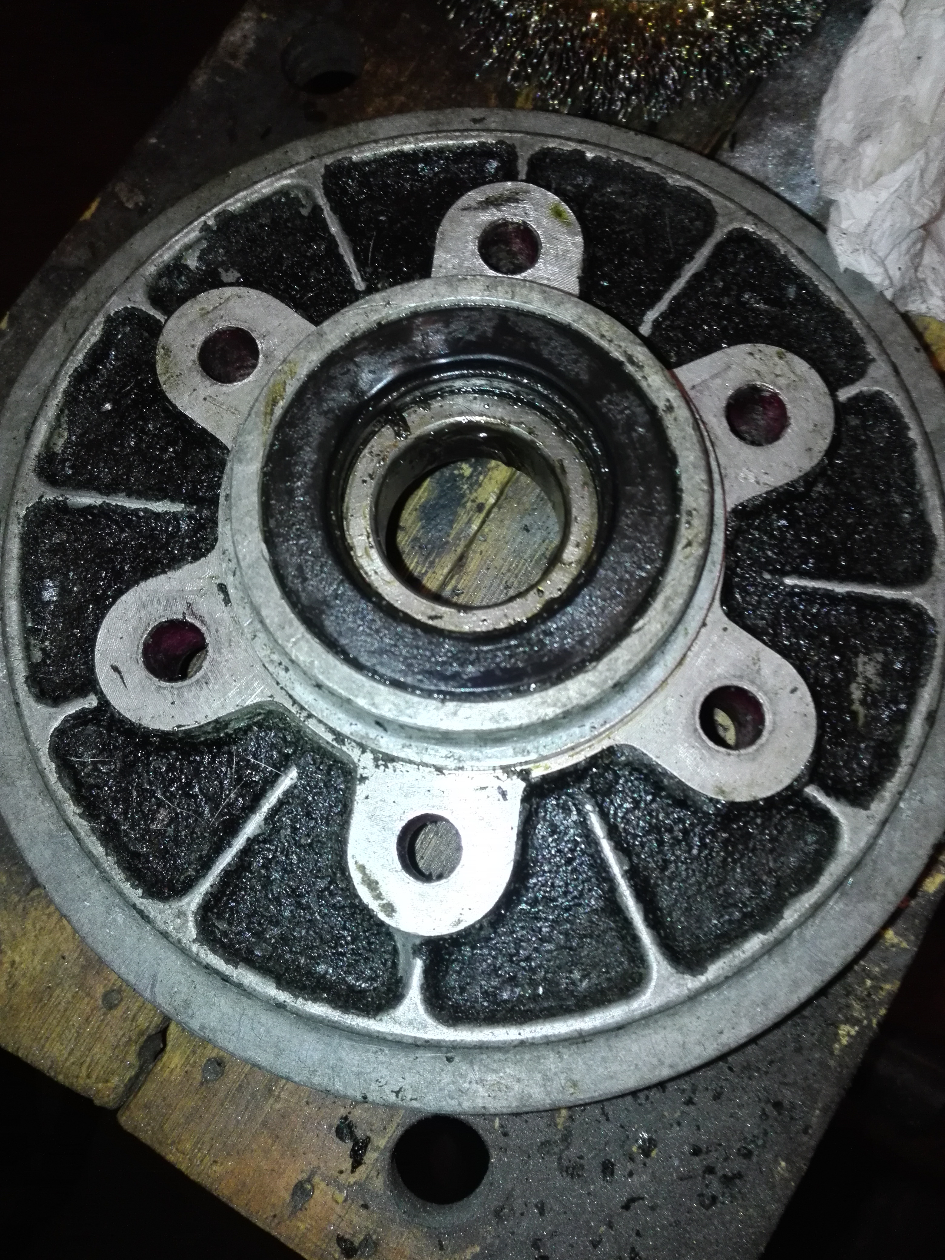
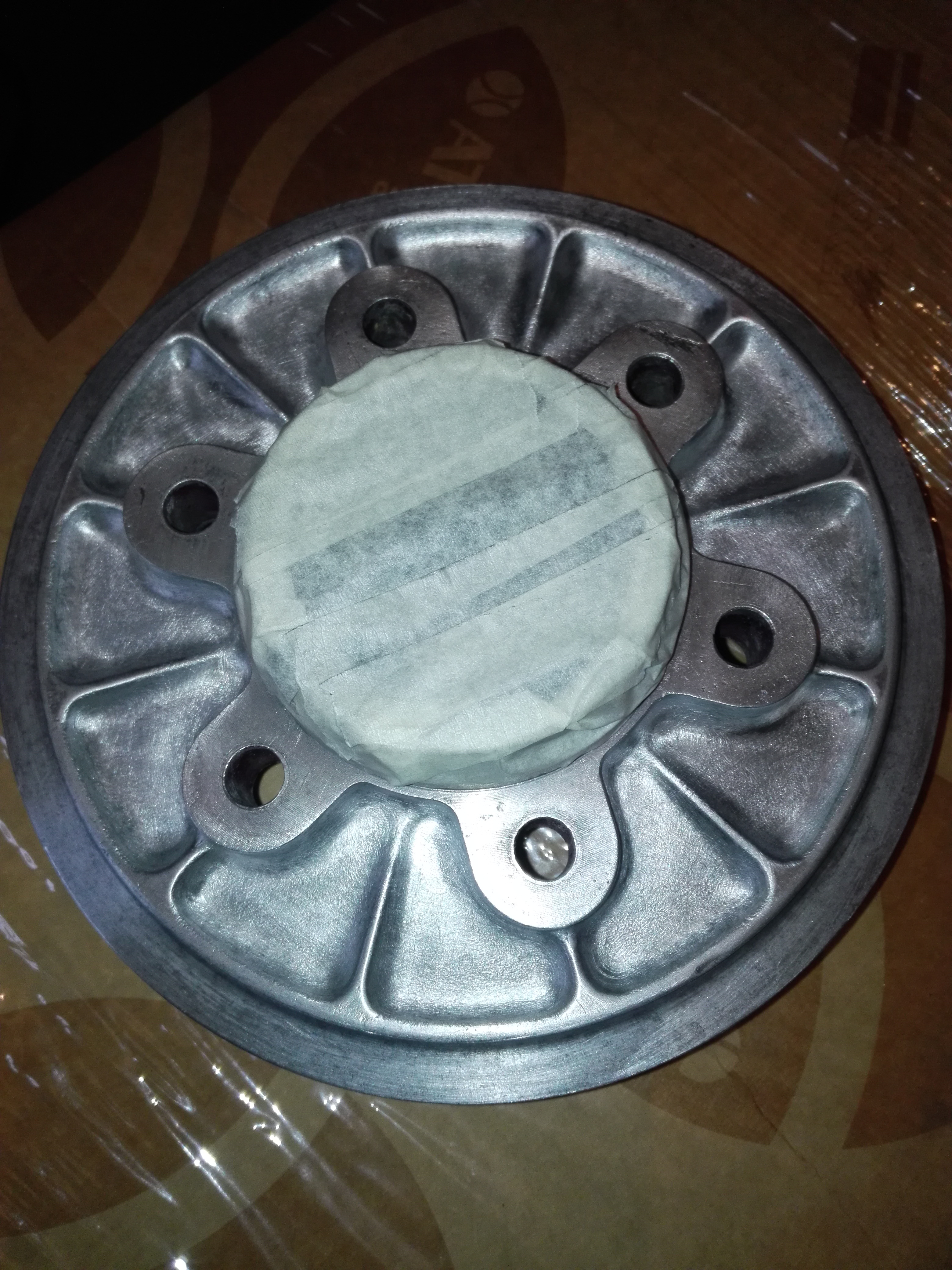
It took ages to get it like this. I followed up with some steel wool and scotch brite. There is still too much oxide to paint this so I decided to just wire brush instead.
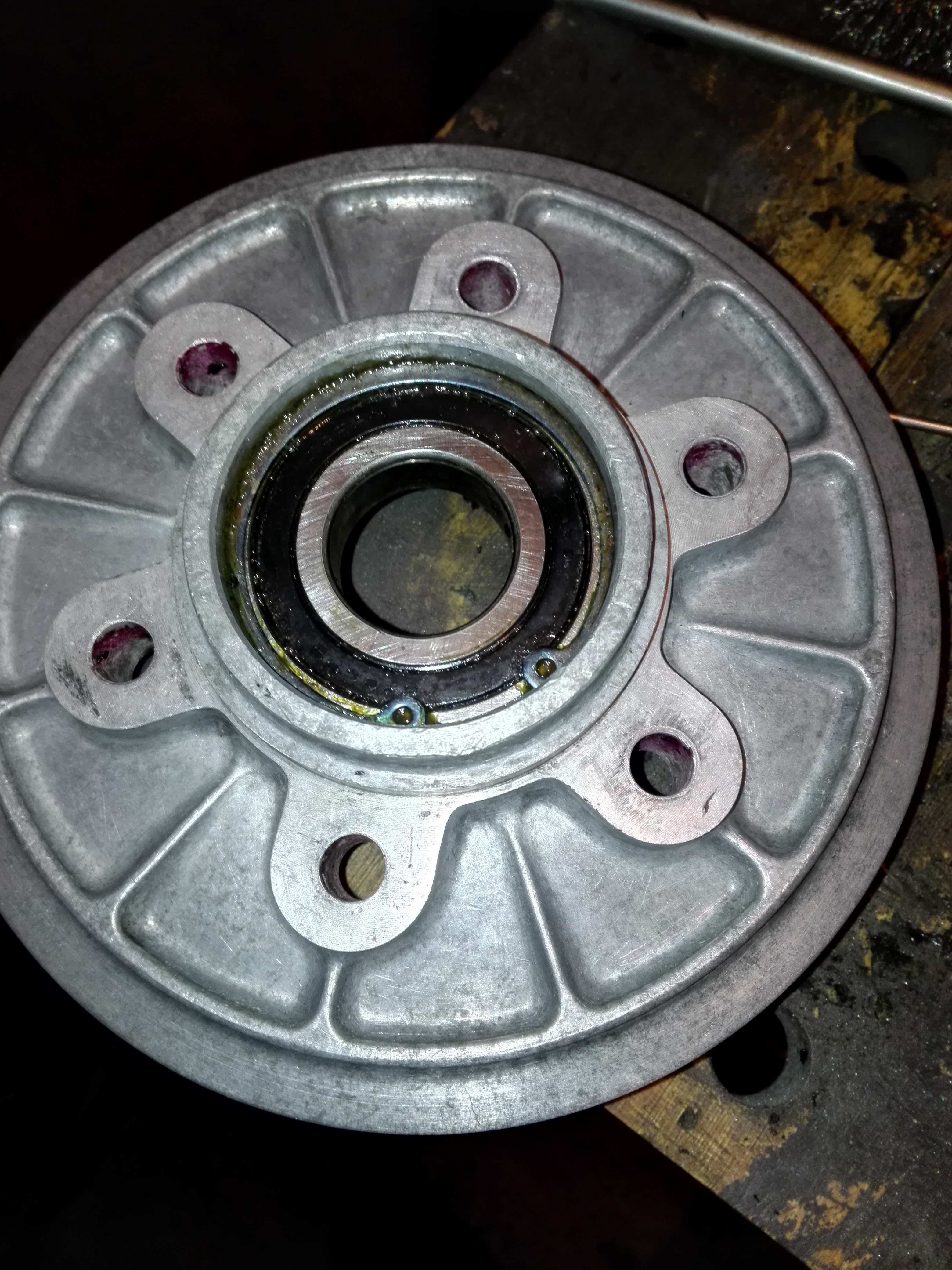
After wire brushing its ready for paint. I also did a bit of sanding to the outer rim. The scratches aren’t too deep for paint to fill.
Masked and ready. I masked up the whole area above the sprocket and I plan to just polish that part after painting.
After a couple of coats of paint
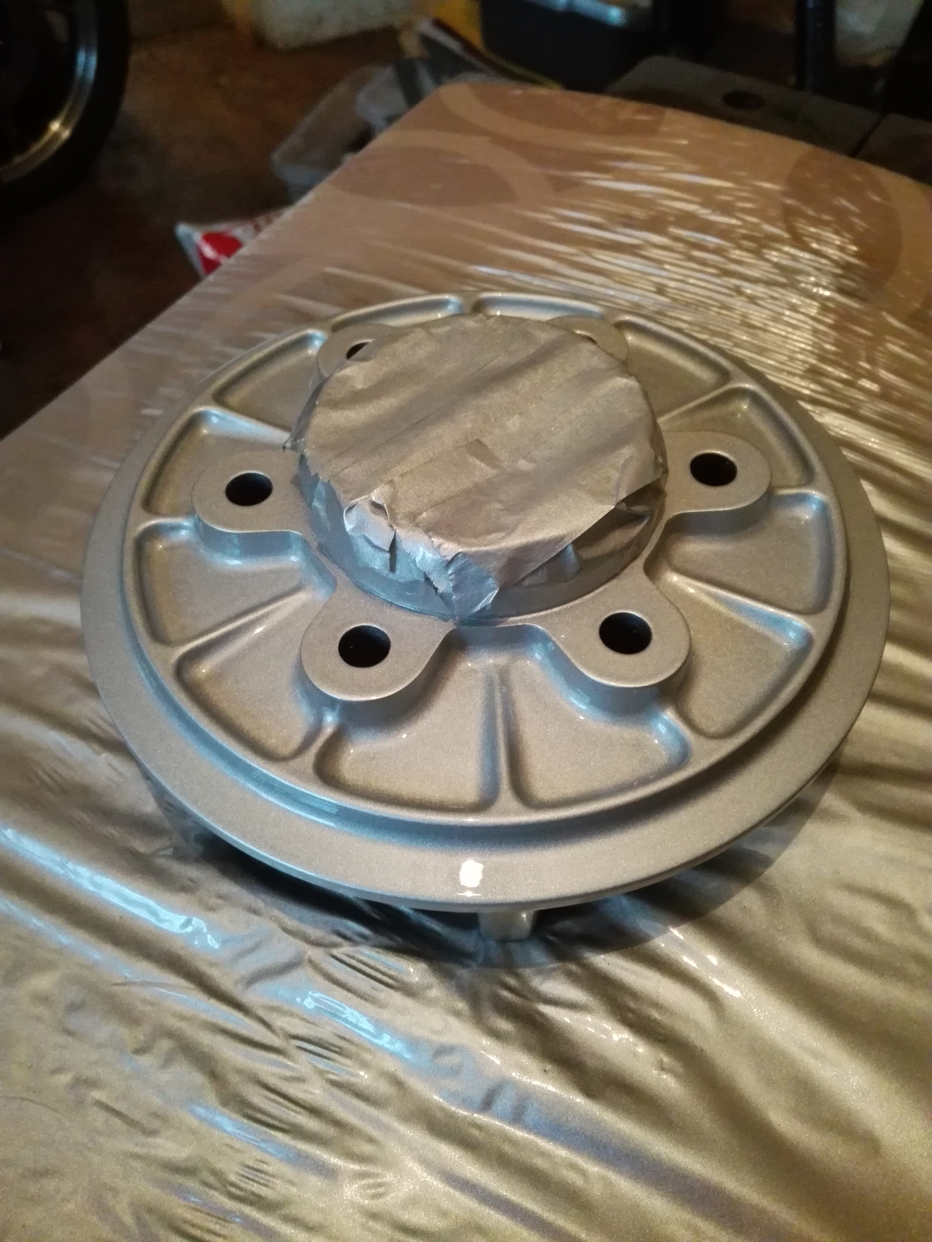
And with the masking removed. Look pretty good I think.
 19th December 2018 at 10:19 pm #24513Ownthesky2010Participant
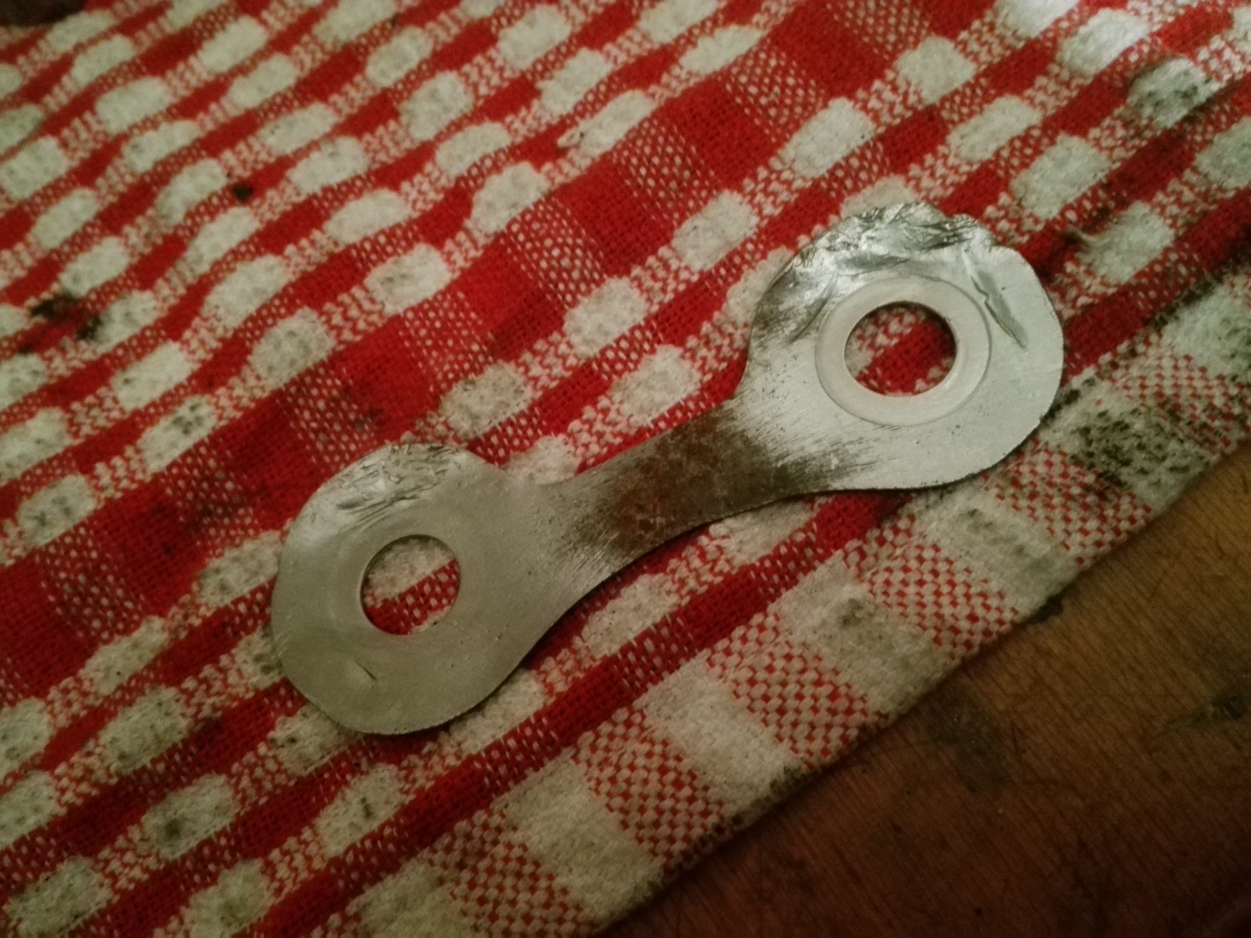
I kept all the hardware for mounting the sprocket as I planned to re-use it all but once I inspected the nuts and bolts they were clearly not in a good state. The threads were quite damaged. I thought I could at least re-use the locking tabs if I flatten them out again so I started cleaning them but I wasn’t really happy with the result.
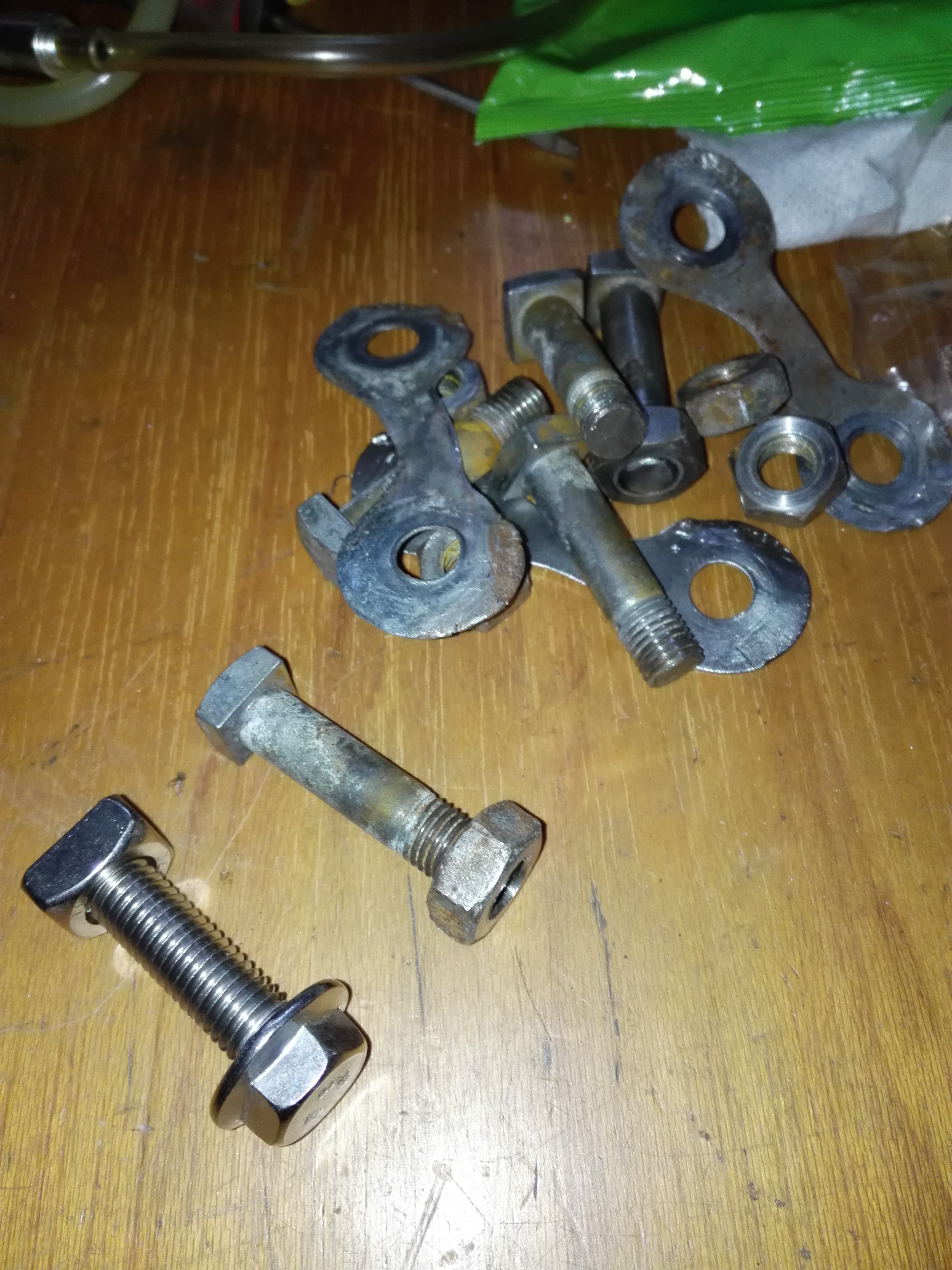
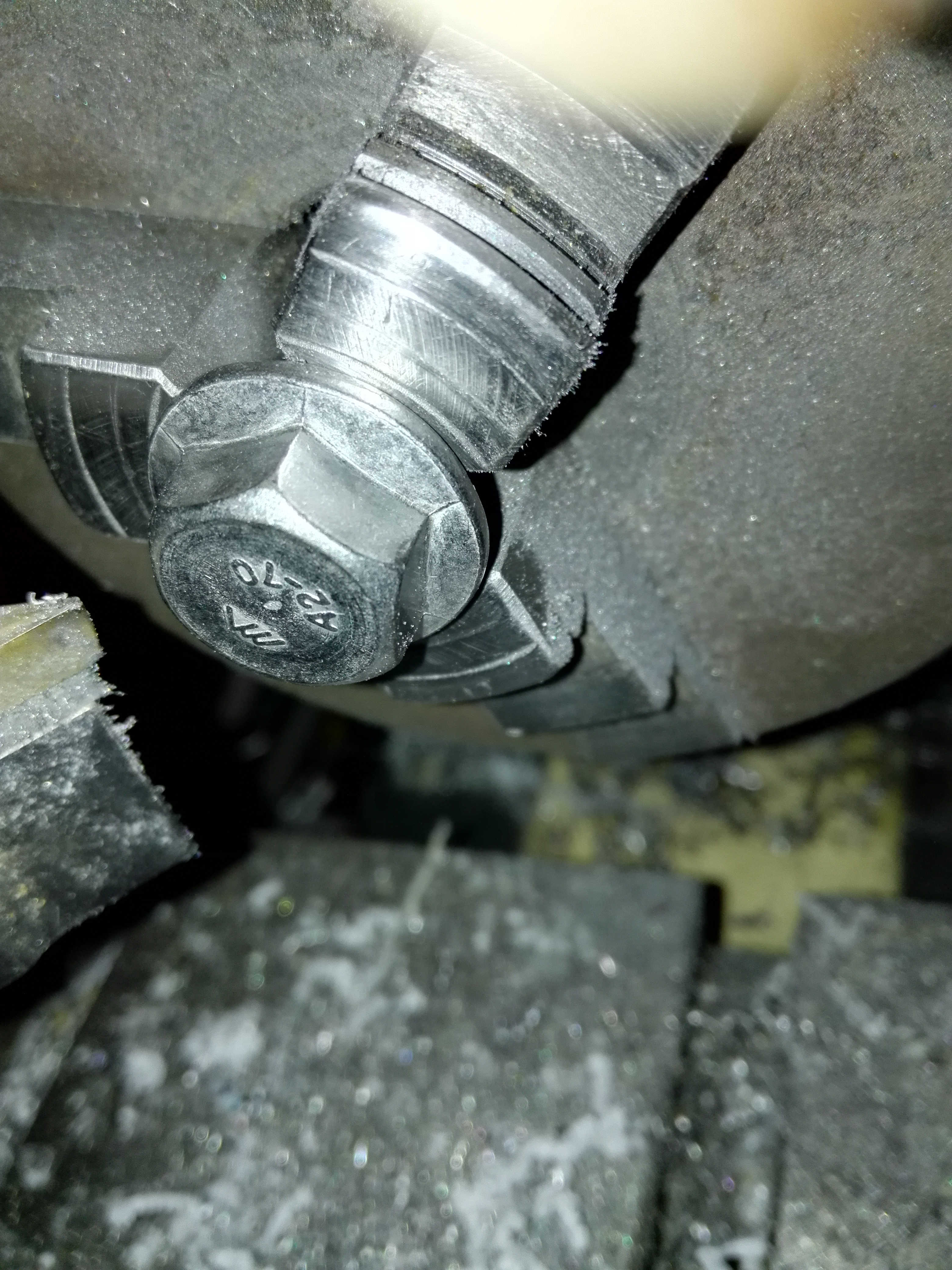
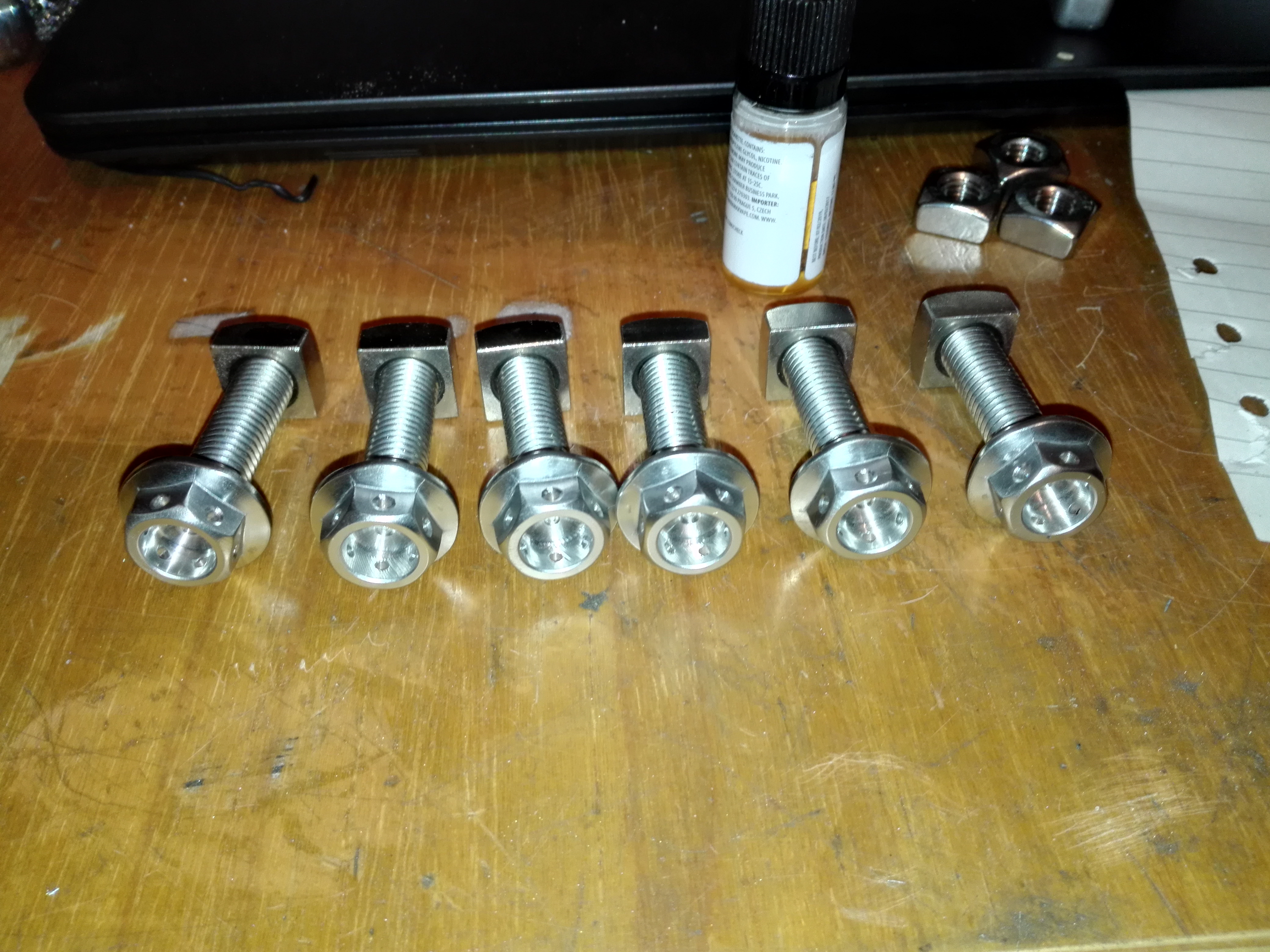
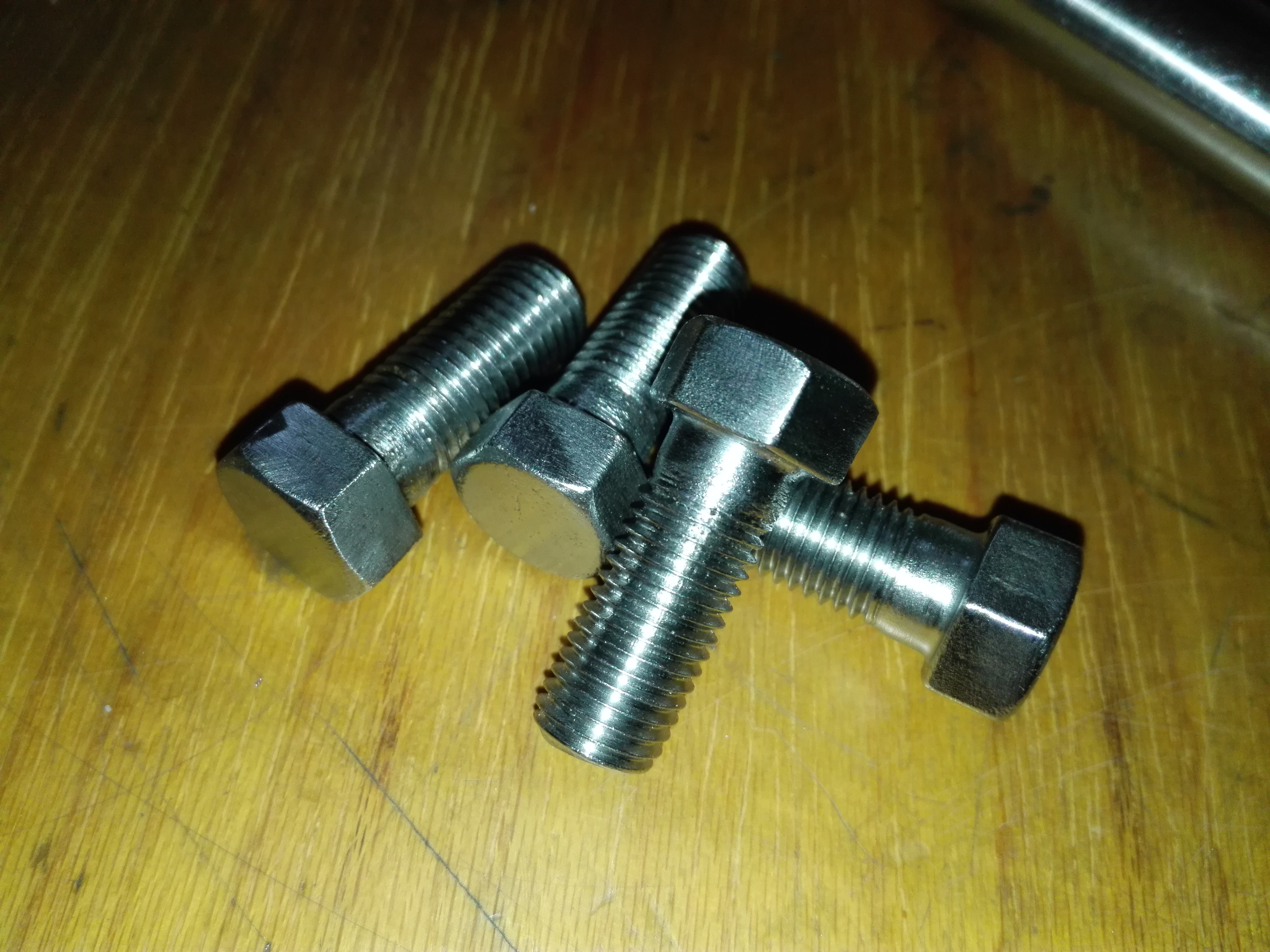
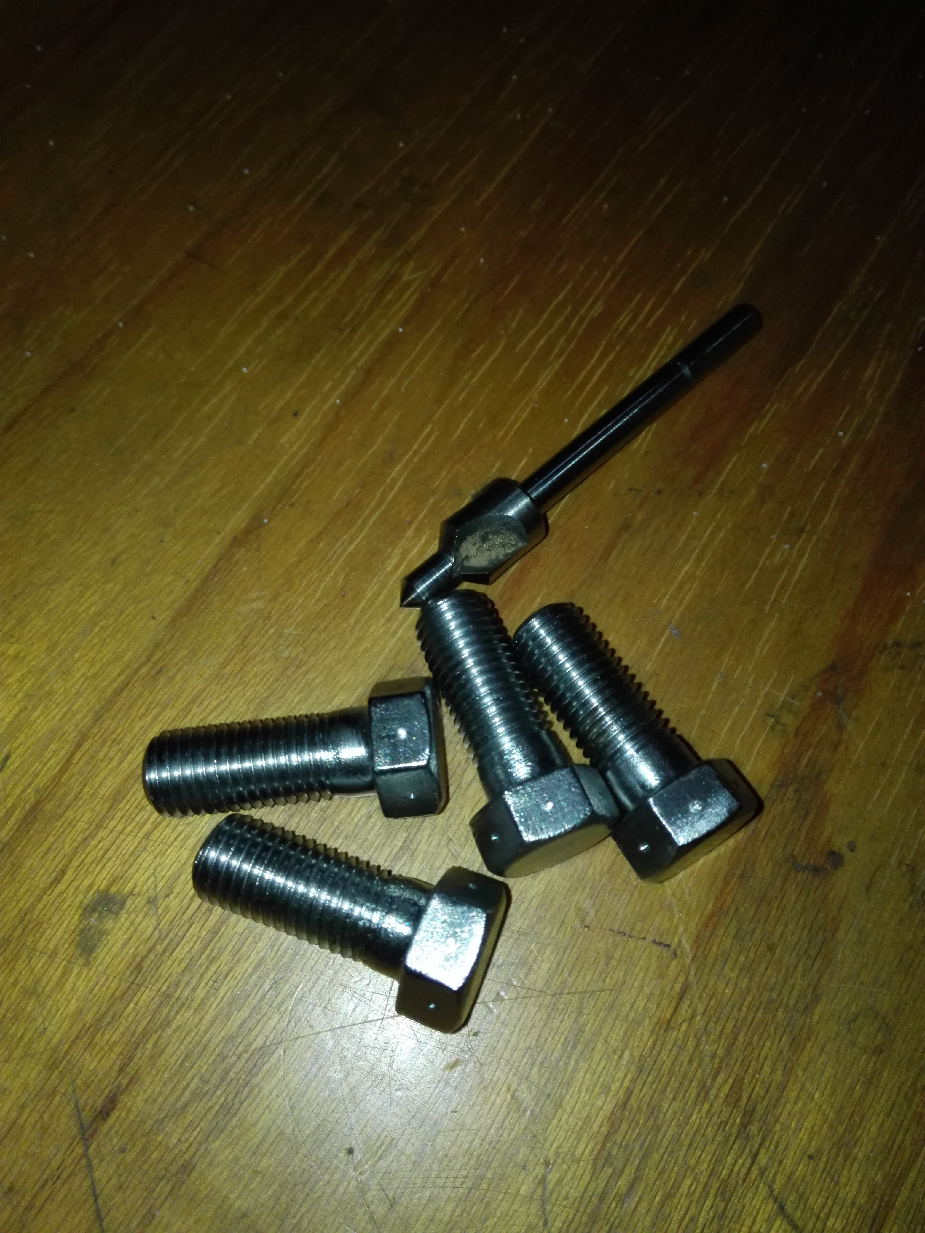
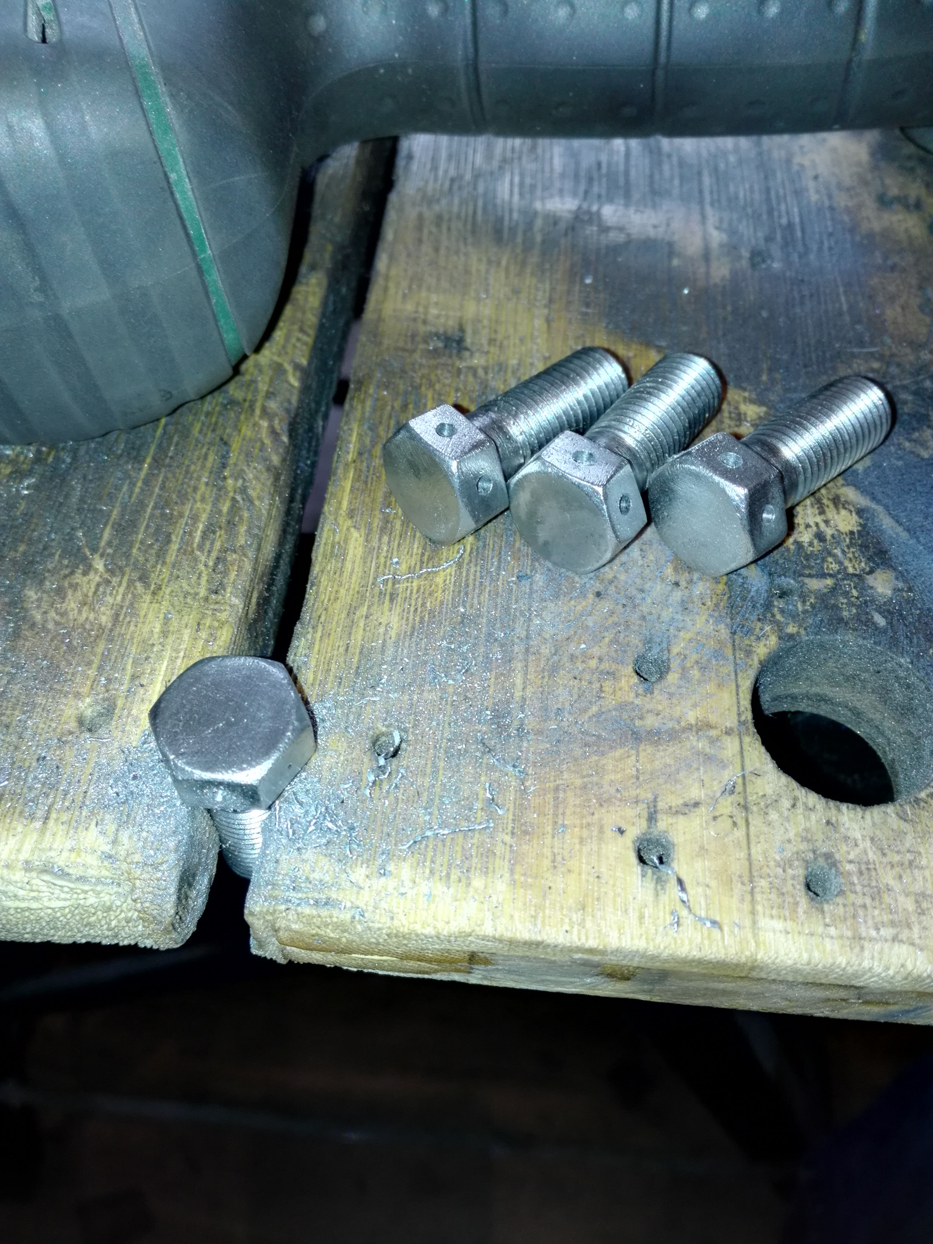
I decided to replace the lot but I didn’t have a lot of success finding the parts so I changed my mind and decided to go with stainless steel. The original bolts have a square head and they are installed from the rear of the carrier with a nut on the outside of the sprocket. Standard stuff. They are M10 fine but I replaced them with standard M10. I had to reverse the fasteners and use a square nut at the back of the carrier and a bolt from the outside of the sprocket. The bolts I like have a large flange so I’m planning to use locking wire instead of tabs because I think it looks cool.
This photo shows the original mounting bolt and nut with the replacement stainless steel units. There is quite a lot of modification required.
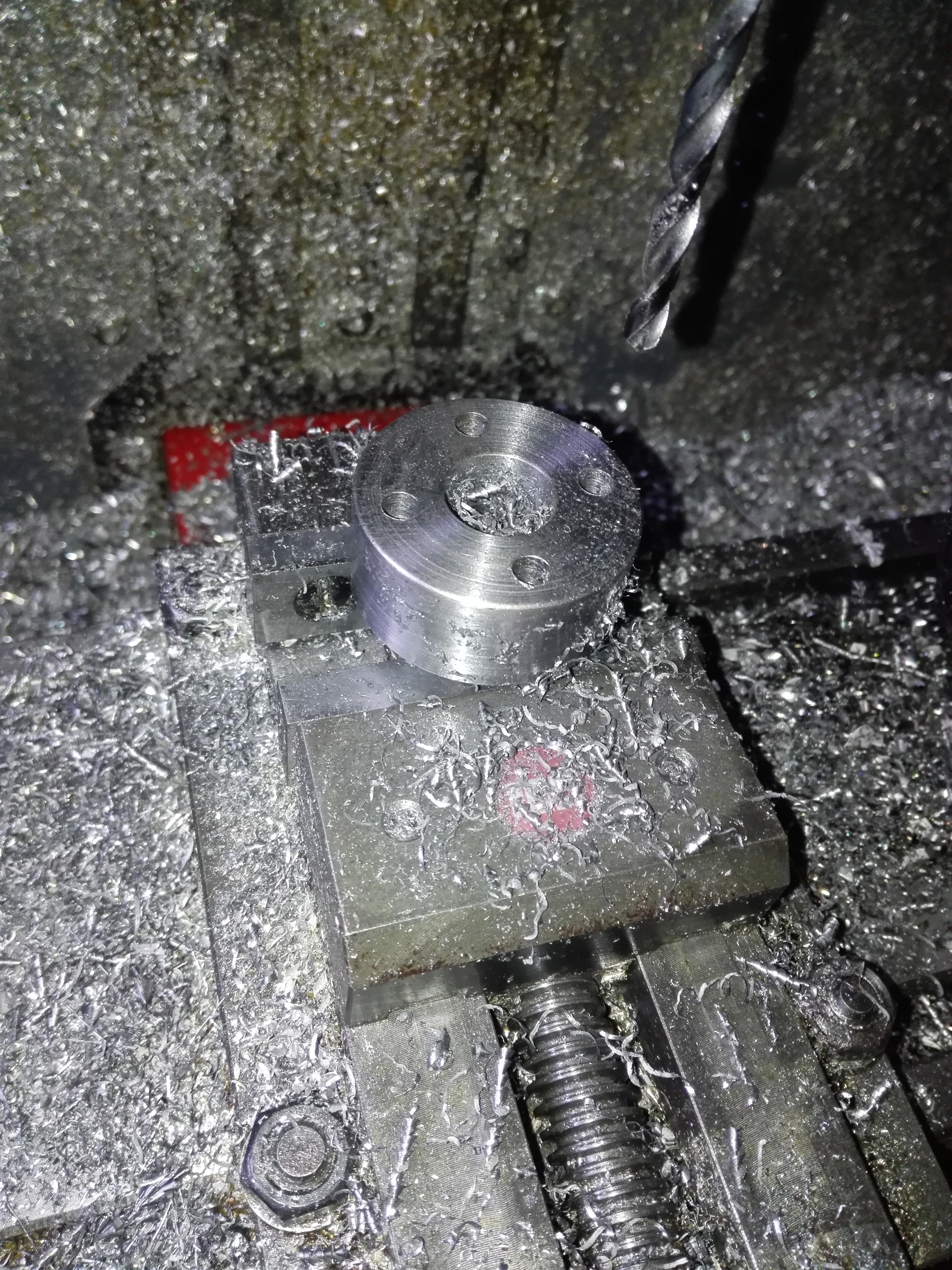
First off the nuts are milled down to fit. I made them a bit bigger than the original bolt heads as they were a bit of a loose fit.
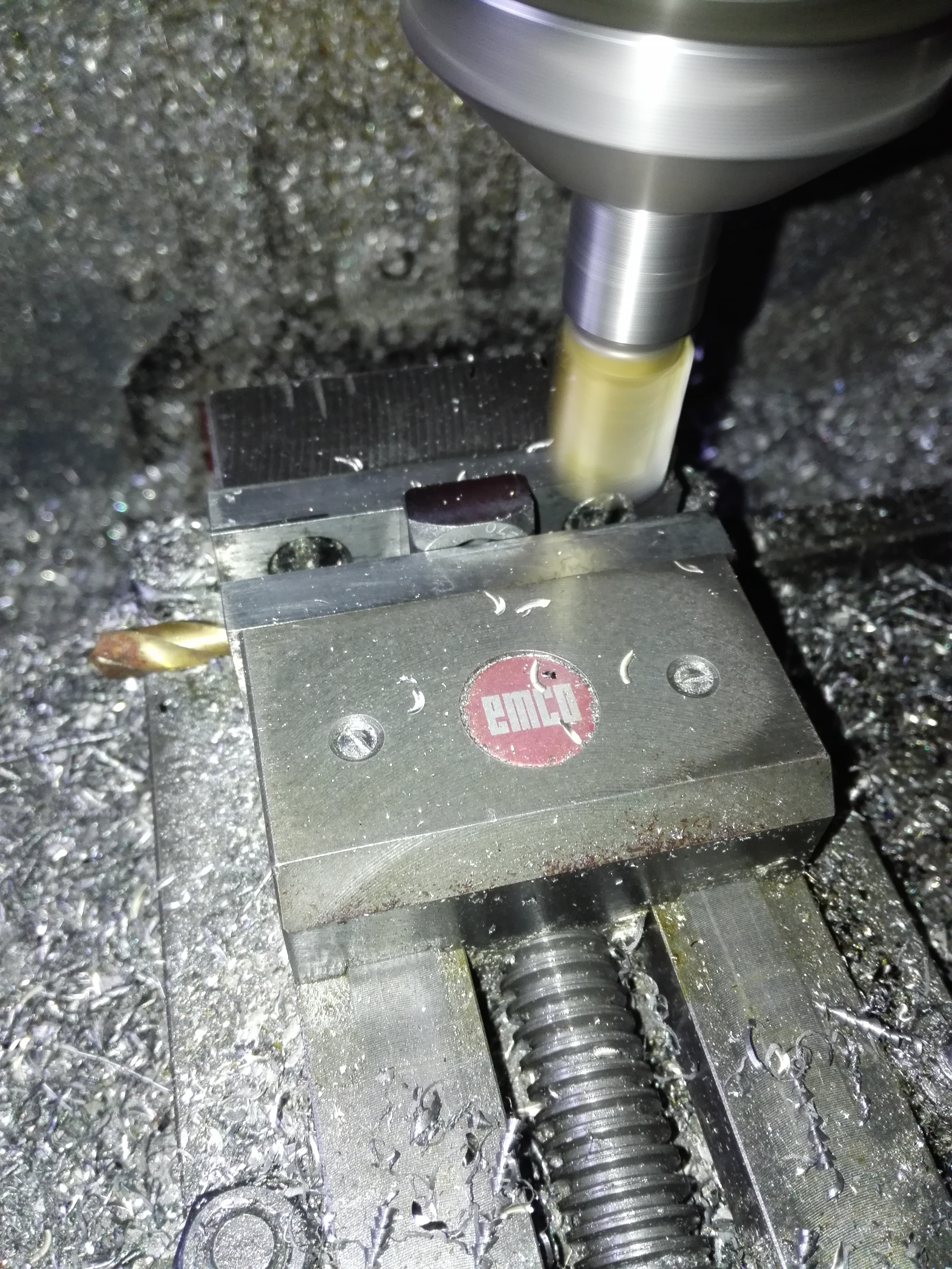
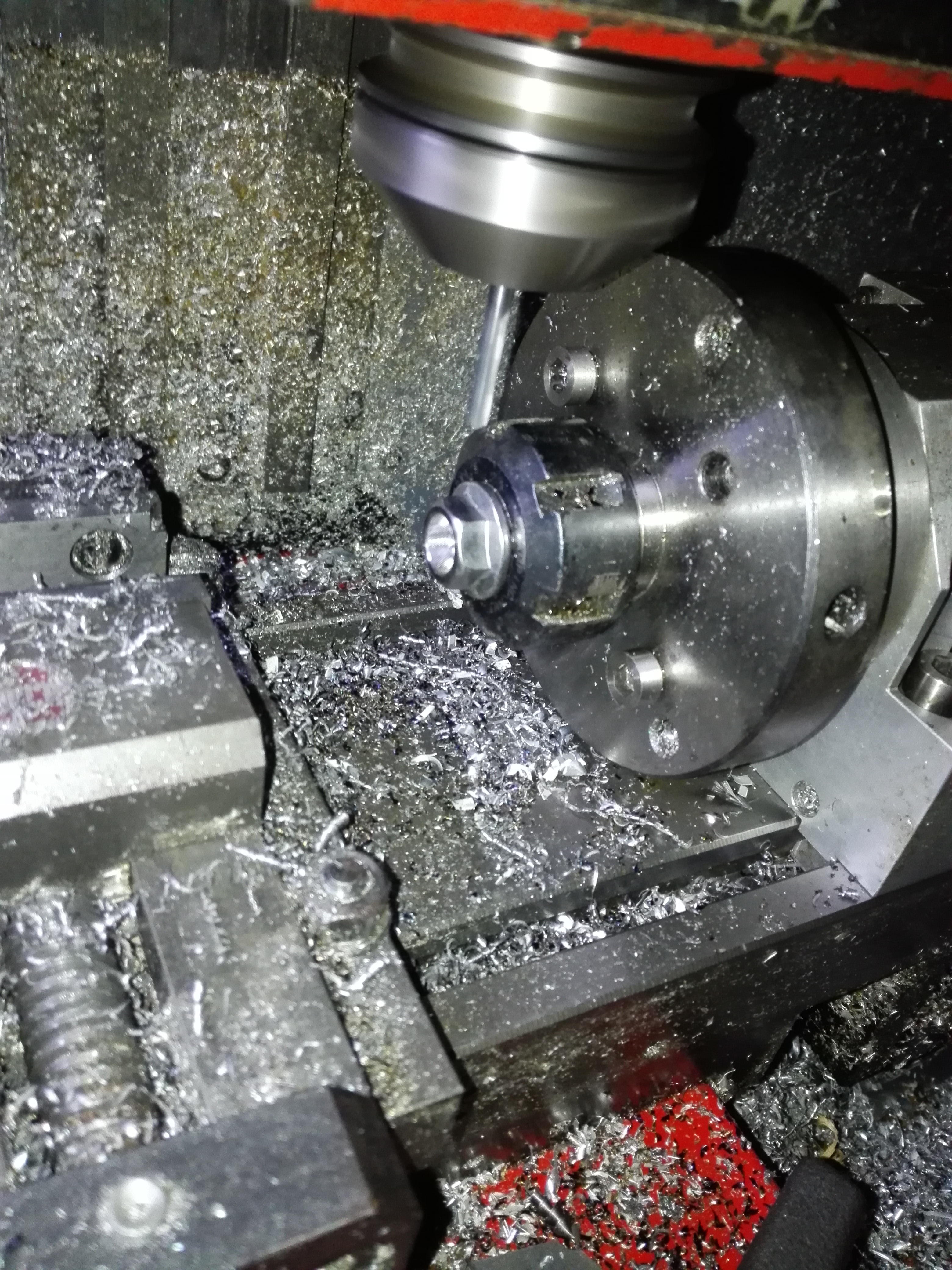
Next I started modding the bolts so they went into the lathe
First the heads were faced clean. At this point I found that the heads had quite a lot of runout. Not good.
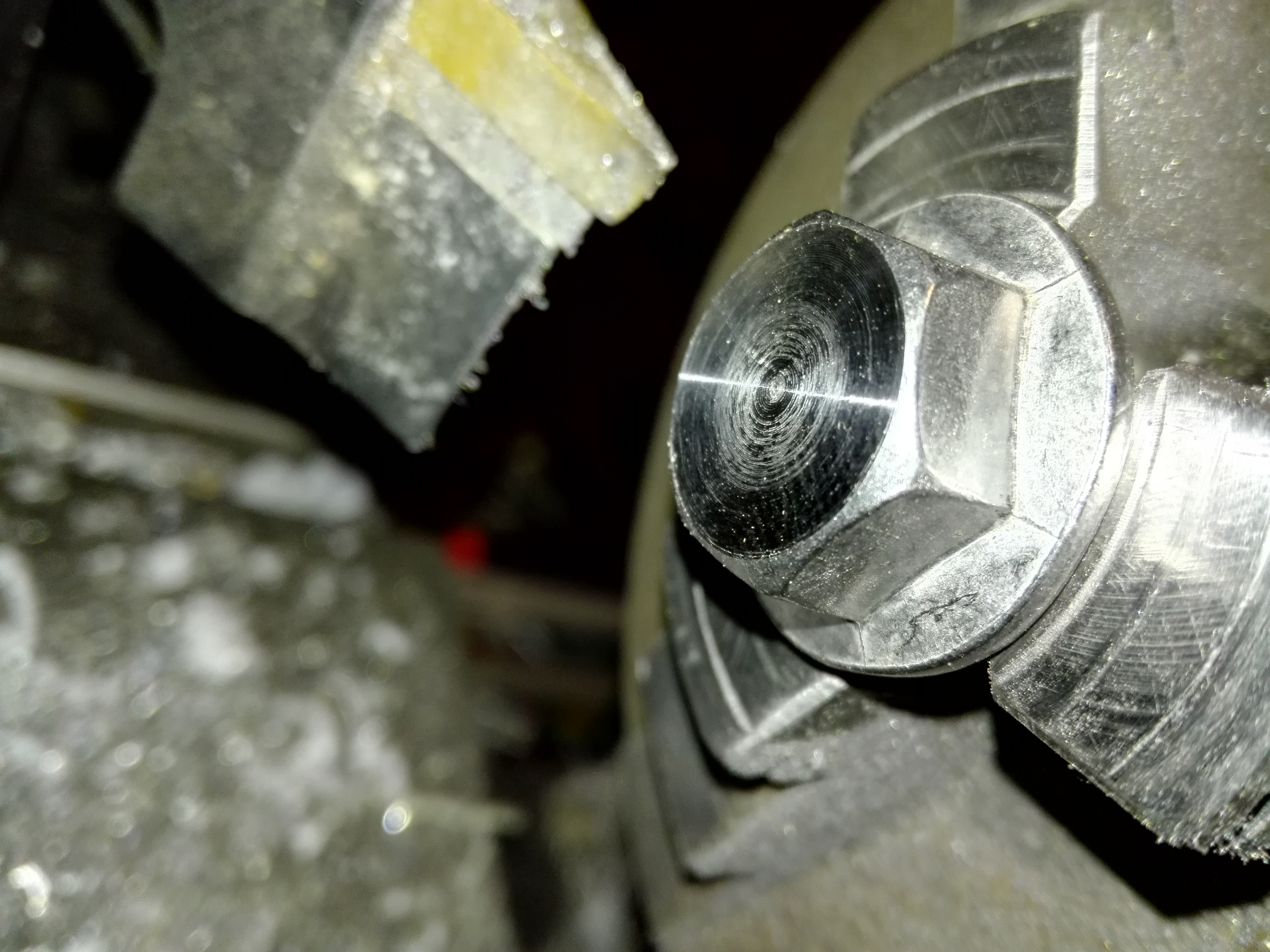
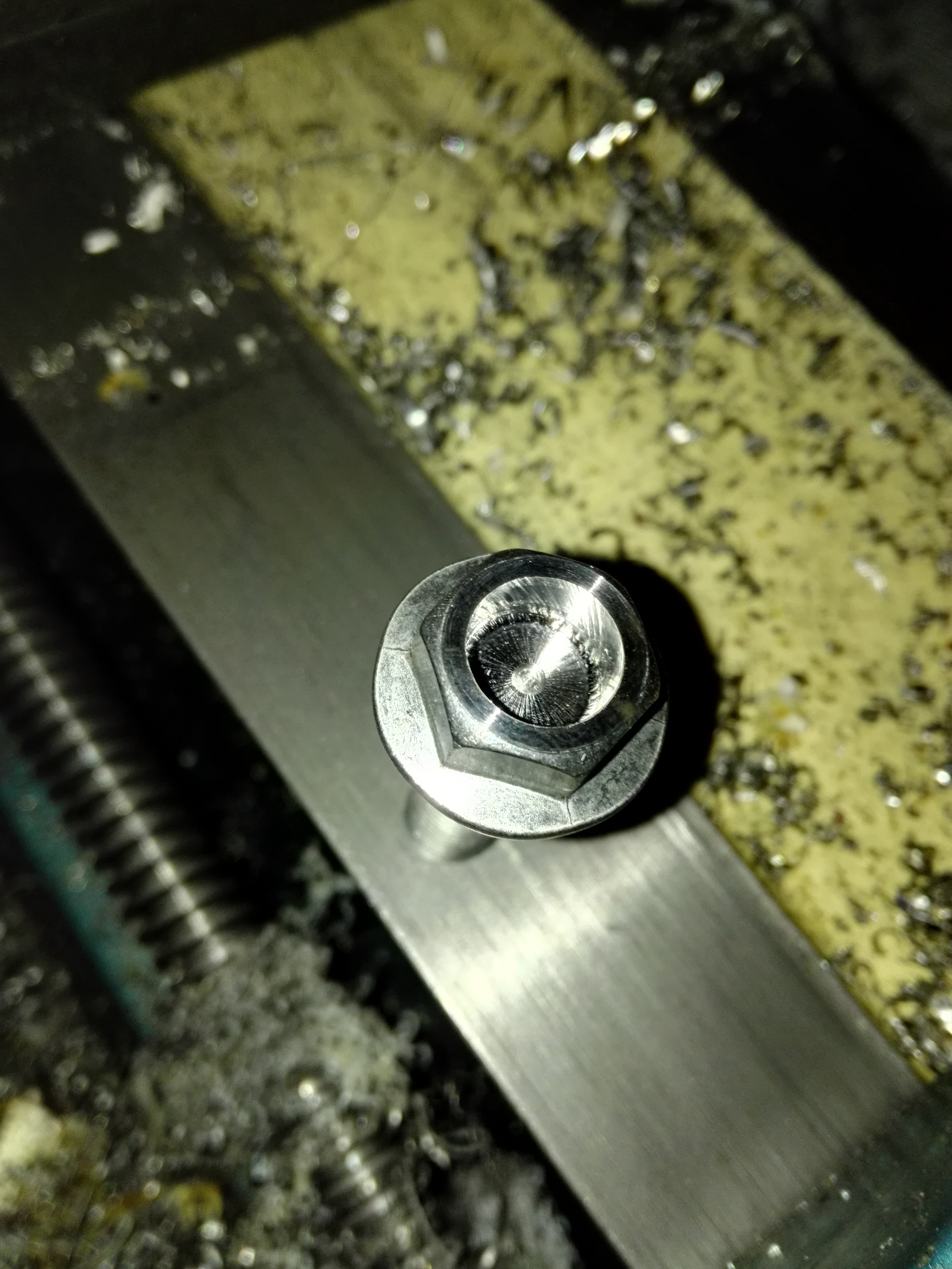
Then I drilled the core out of the heads with an 8mm drill and finished with a 10mm end mill to create a flat bottomed hole. This is mainly to make it easier to drill the holes for the locking wire.
Next they went into the rotary table in the miller for the holes. I was only doing spot drilling to locate the holes to be hand drilled as the holes are quite small and I didn’t want to break any drills. There was so much run-out in the bolt heads that I had to do this manually. If I had programmed this operation the depth would have been allover the place. As it went, most of the holes were quite far off the center.
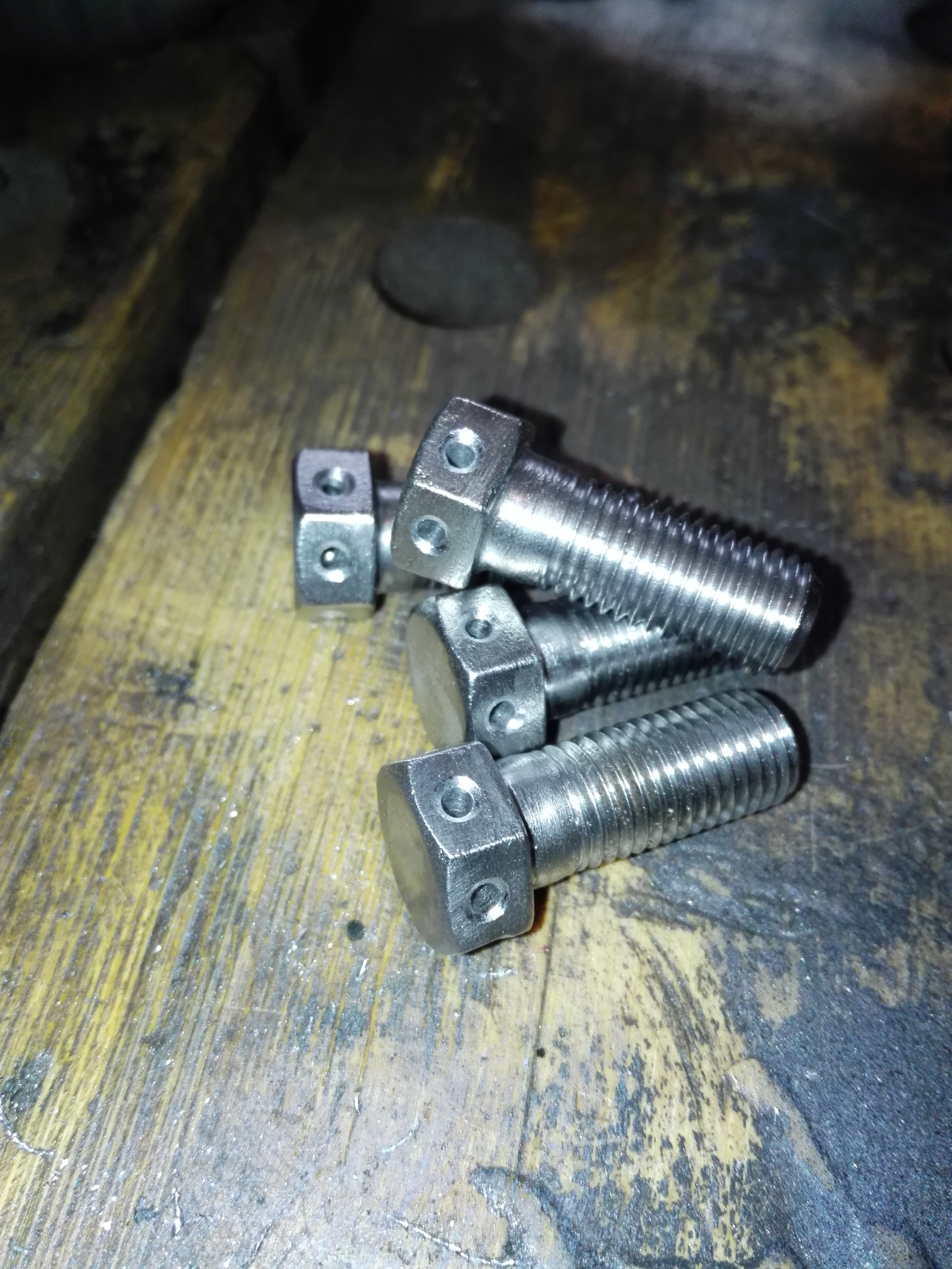
The bolts are now spot drilled ready to be drilled through.
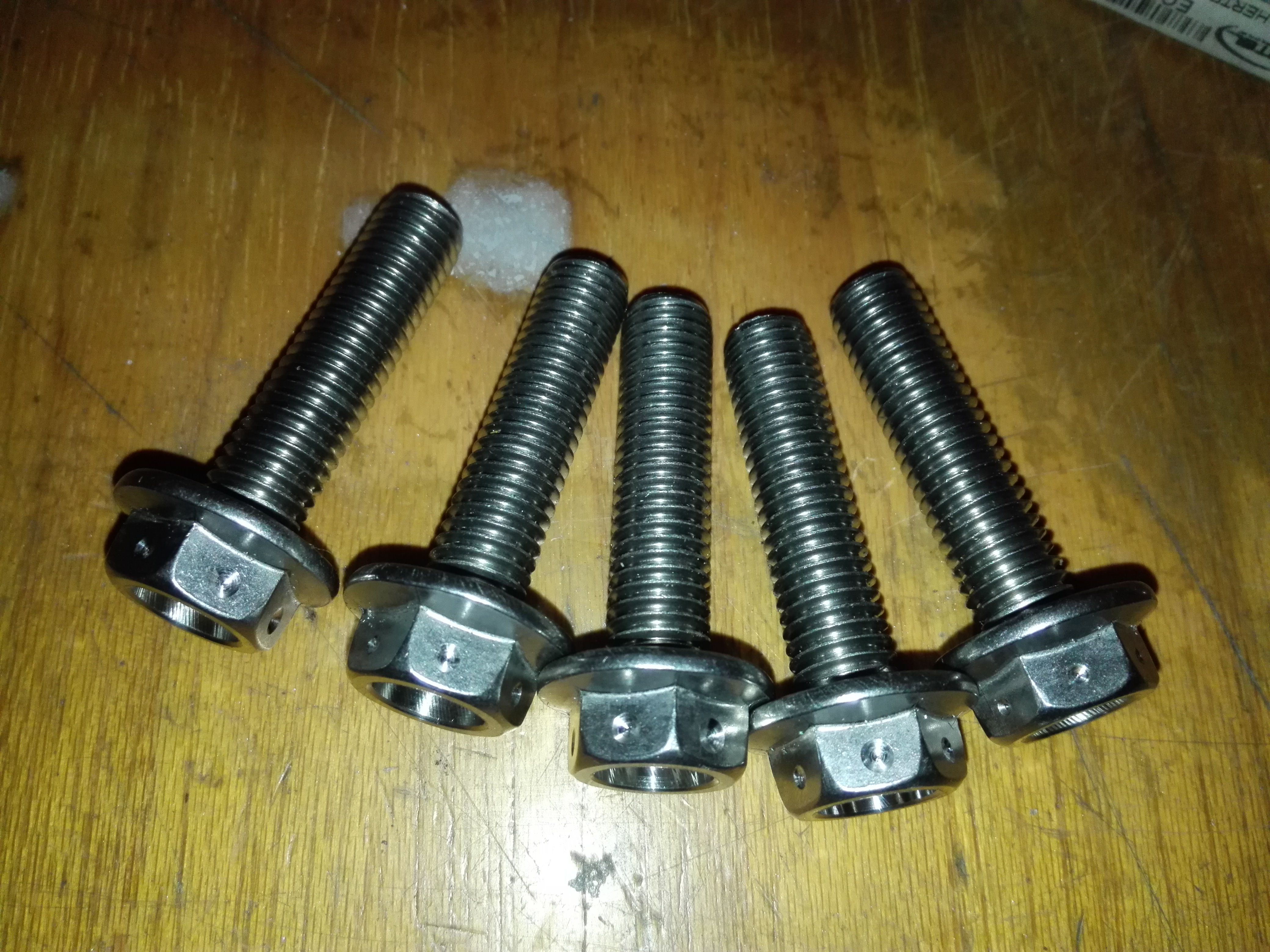
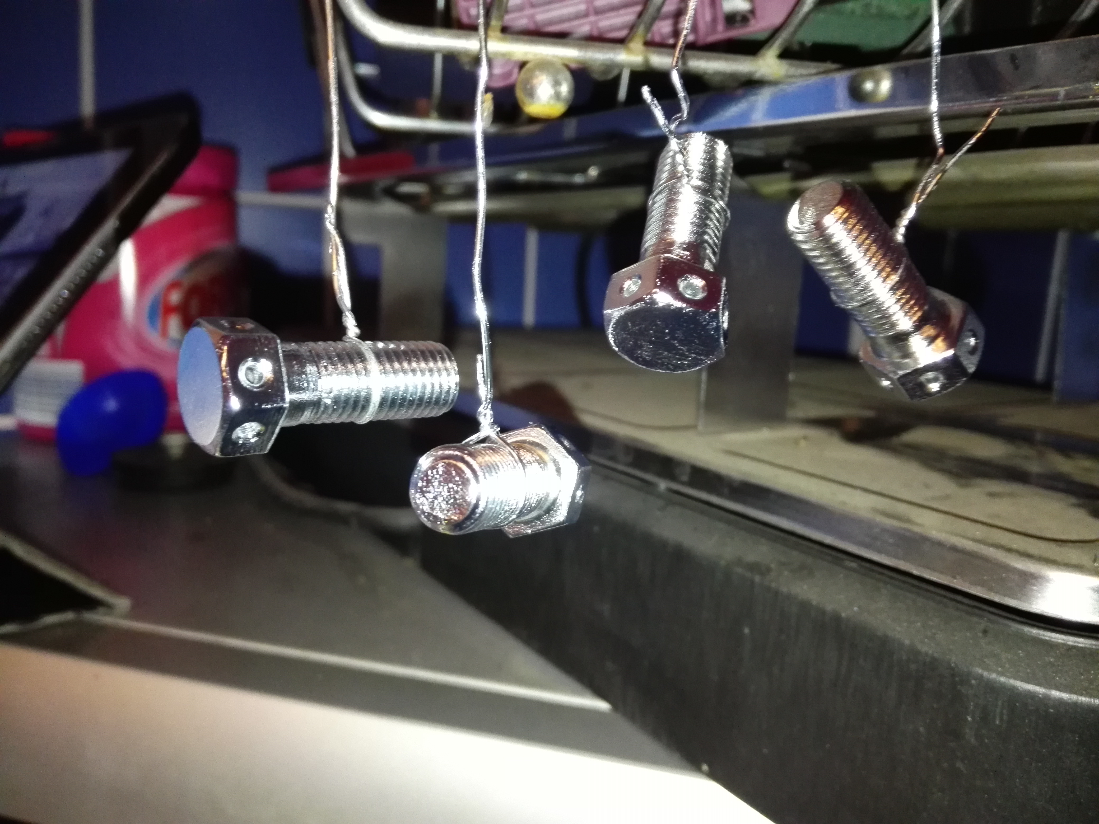
And then all drilled through with their nuts, ready to fit. I gave them a once over with the scotch brite wheel but I didn’t polish them.
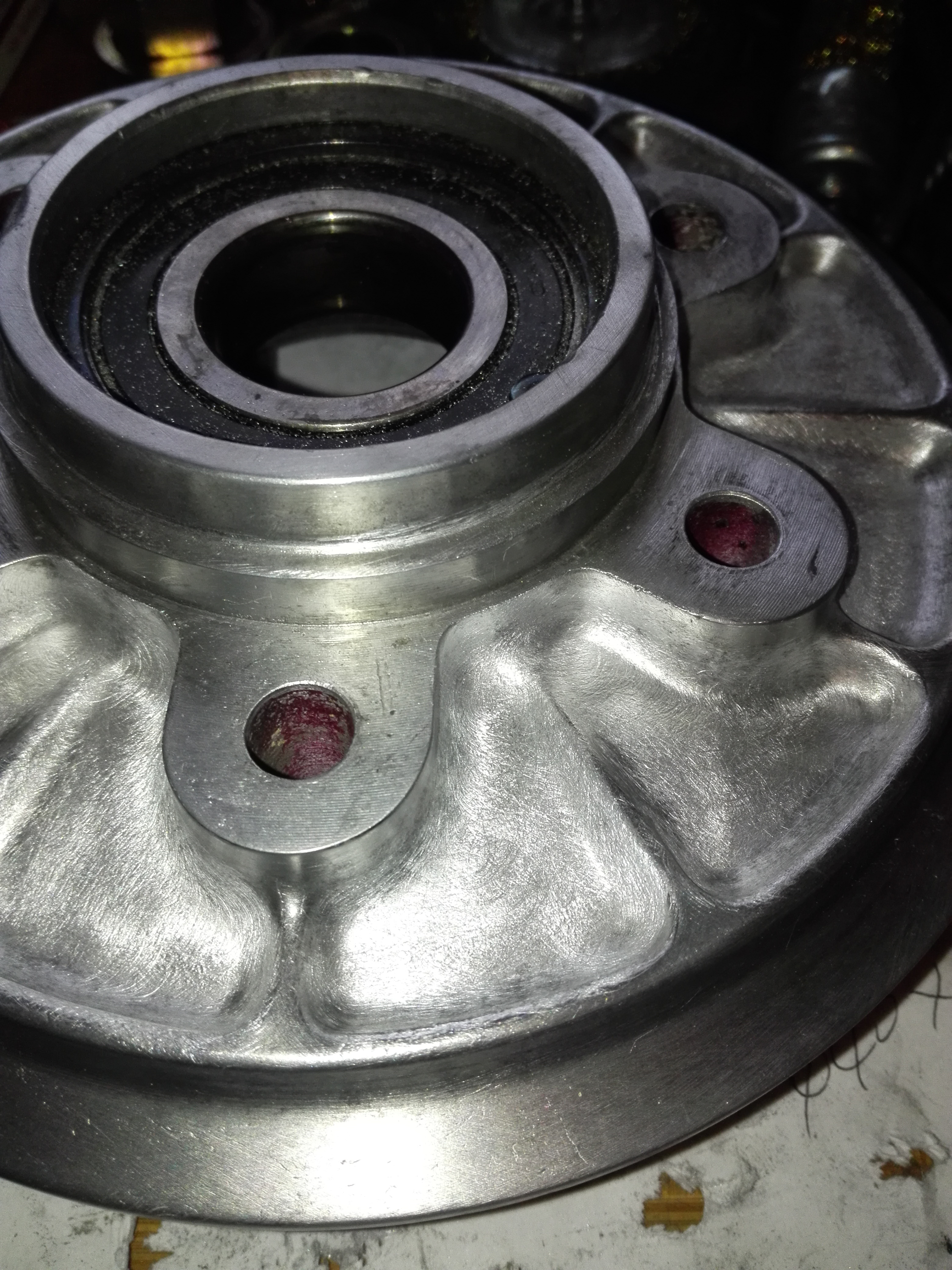
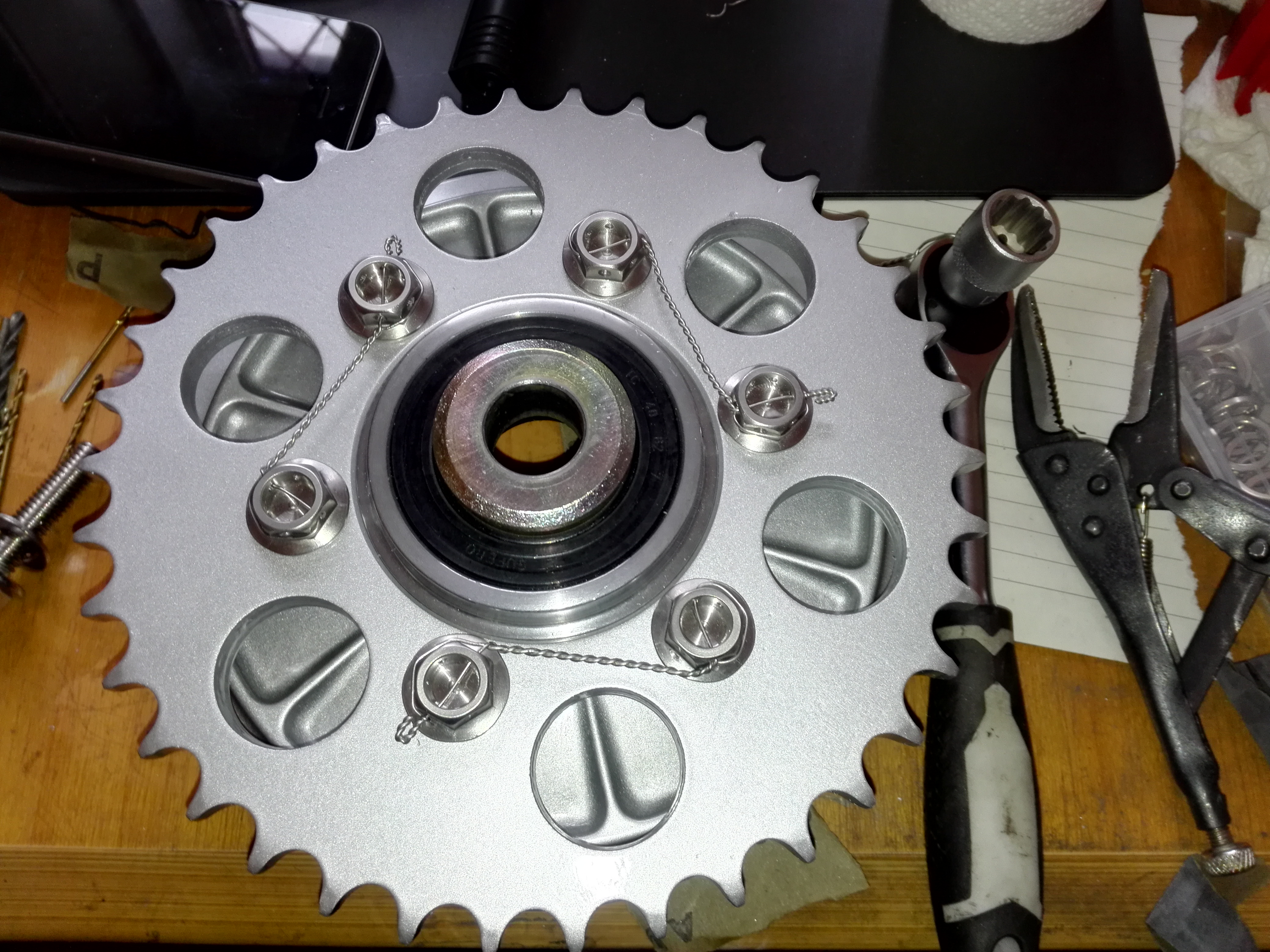
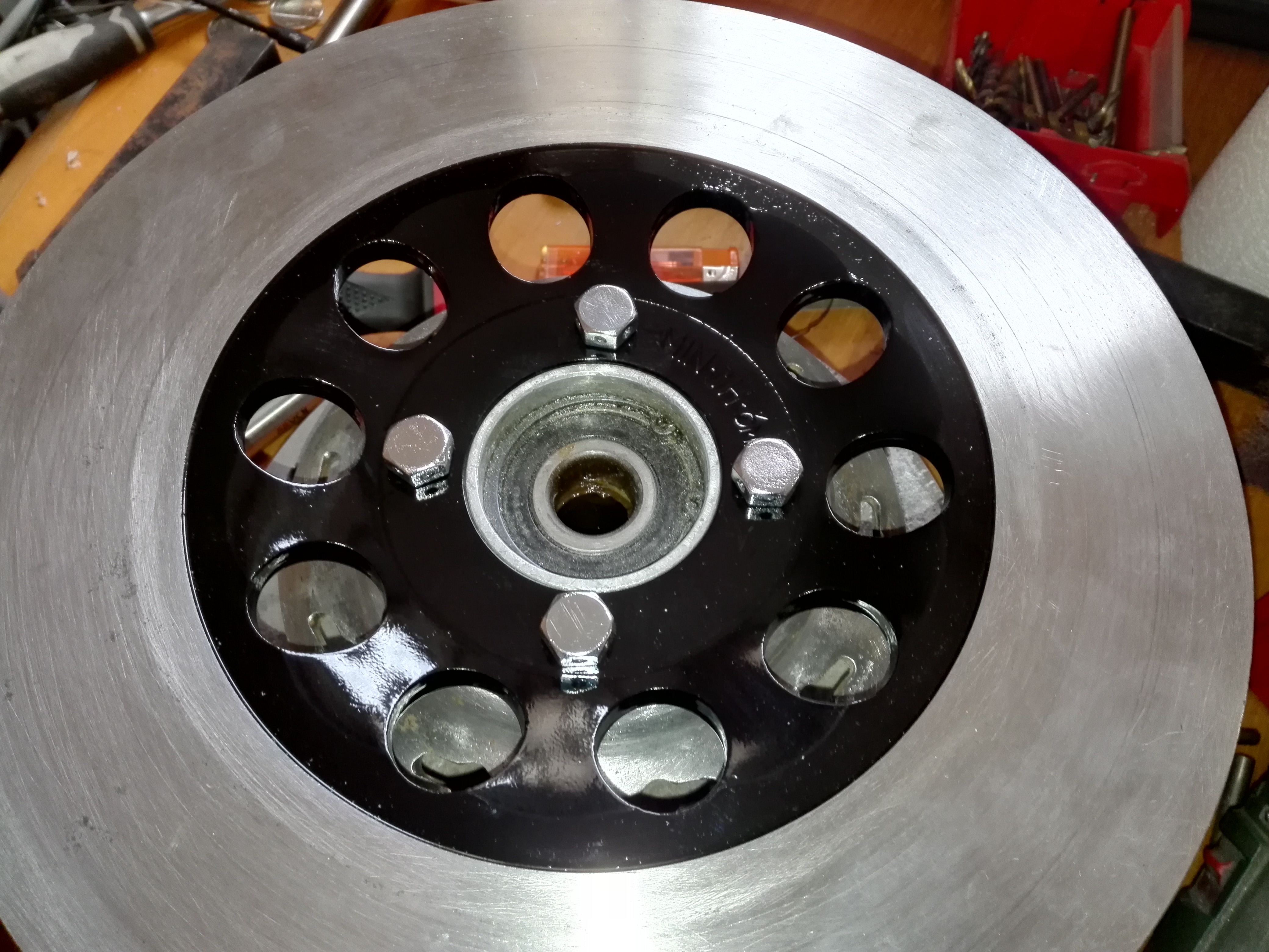
I polished the center of the sprocket carrier and fitted a new seal and then installed the sprocket. Looking good so far. The bearing feels fine so I see no reason to change it.
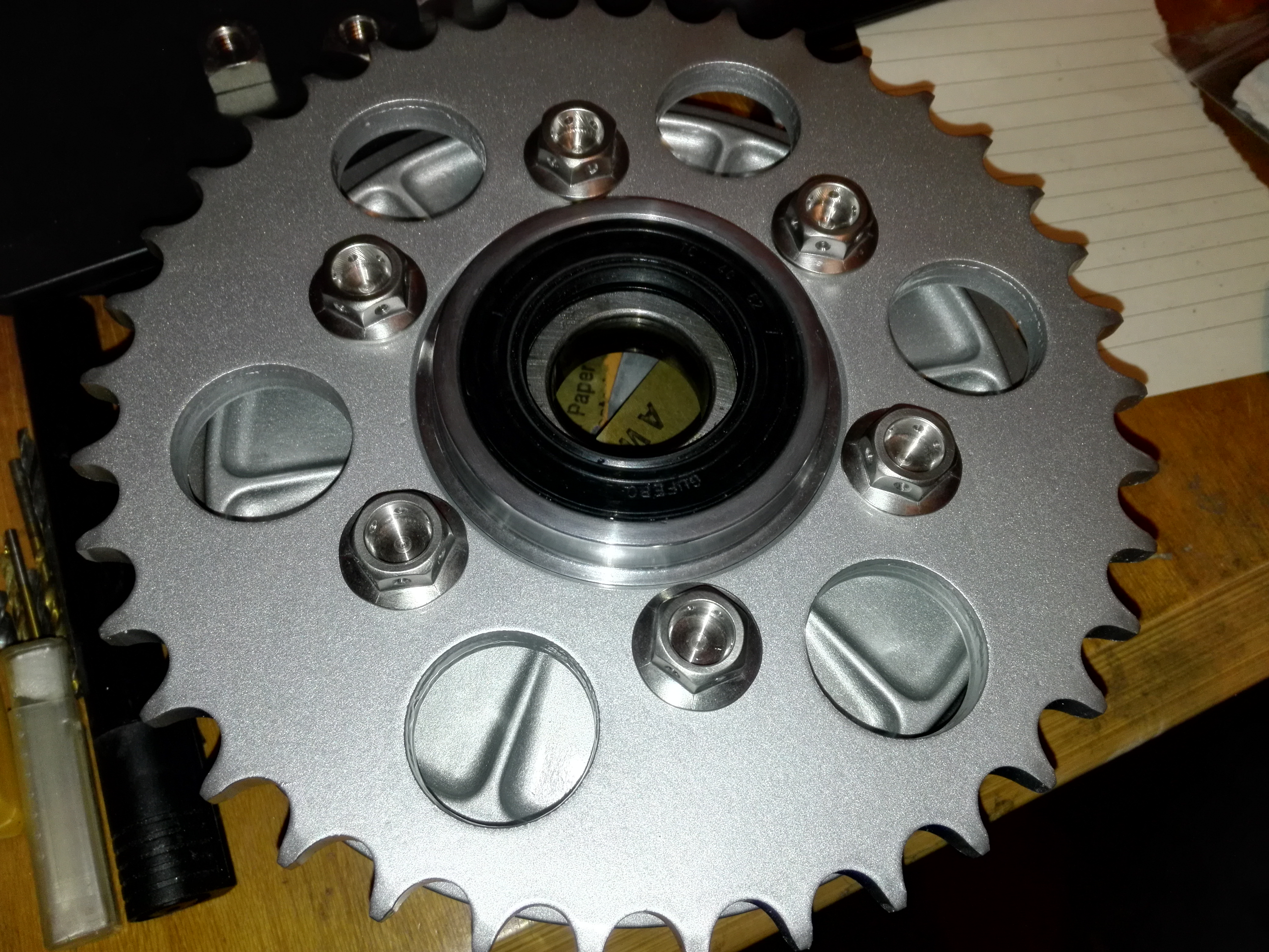
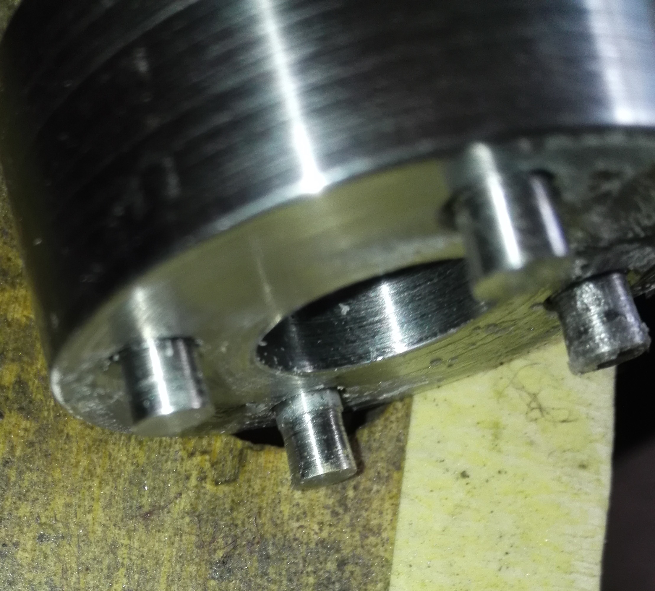
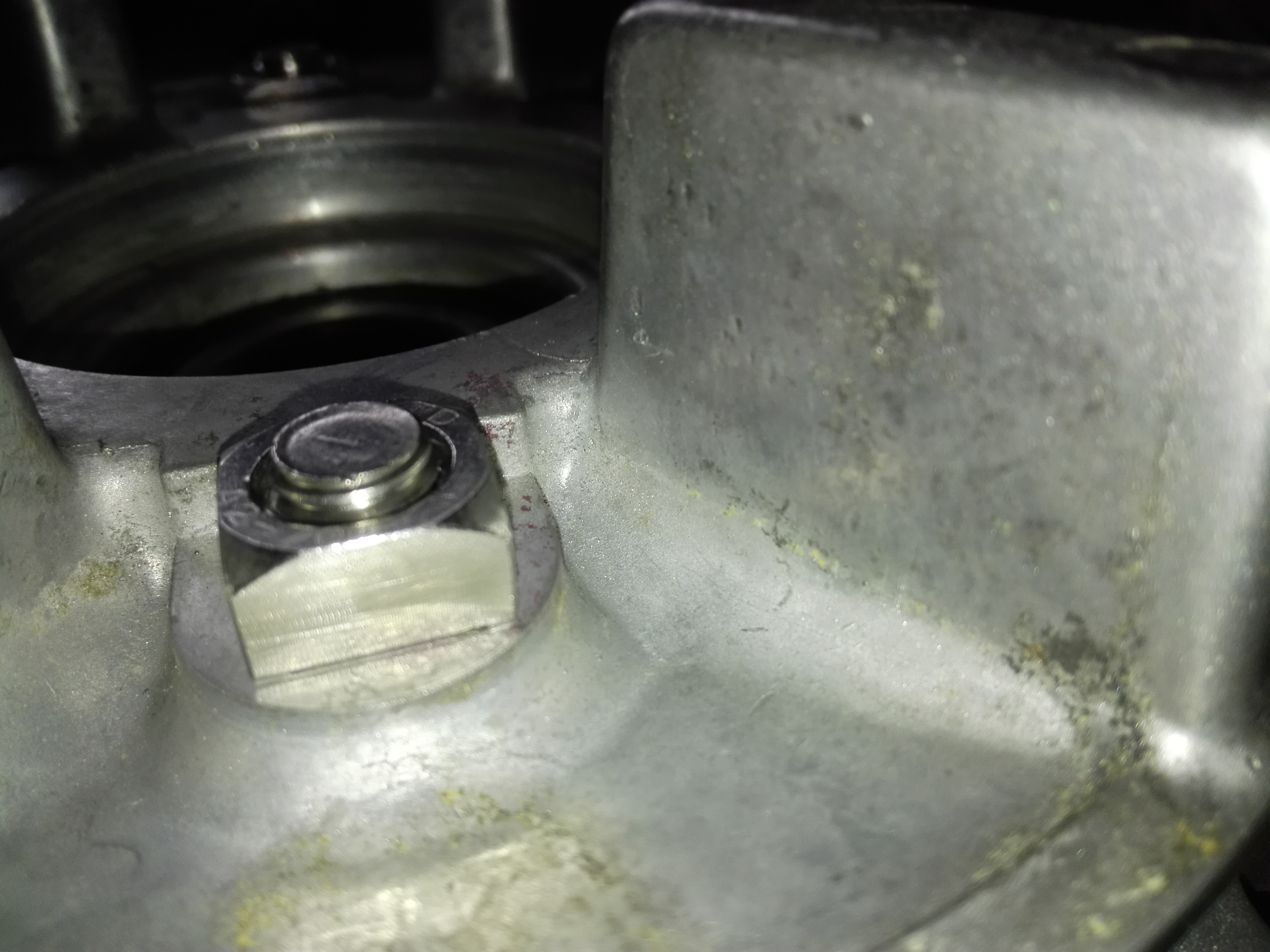
A view from the back showing the new nuts.
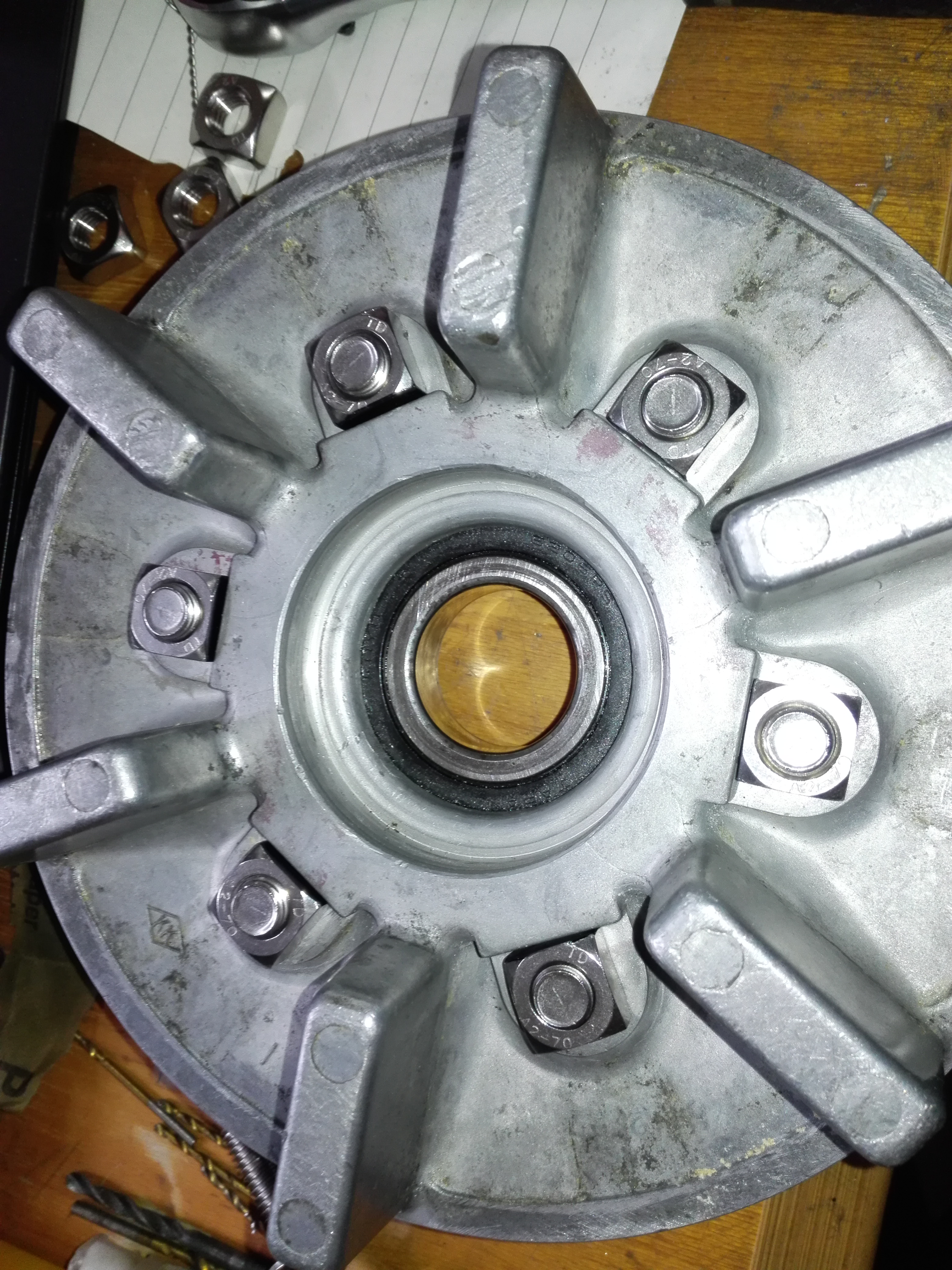
They are a little taller than the original hardware but I’m hoping they will just compress the rubber dampers a bit more.
And finally wired up. I haven’t done much bolt wiring before but I’m happy with the result. Compare this with the way it looked before 🙂
 23rd December 2018 at 12:12 am #24565Ownthesky2010Participant
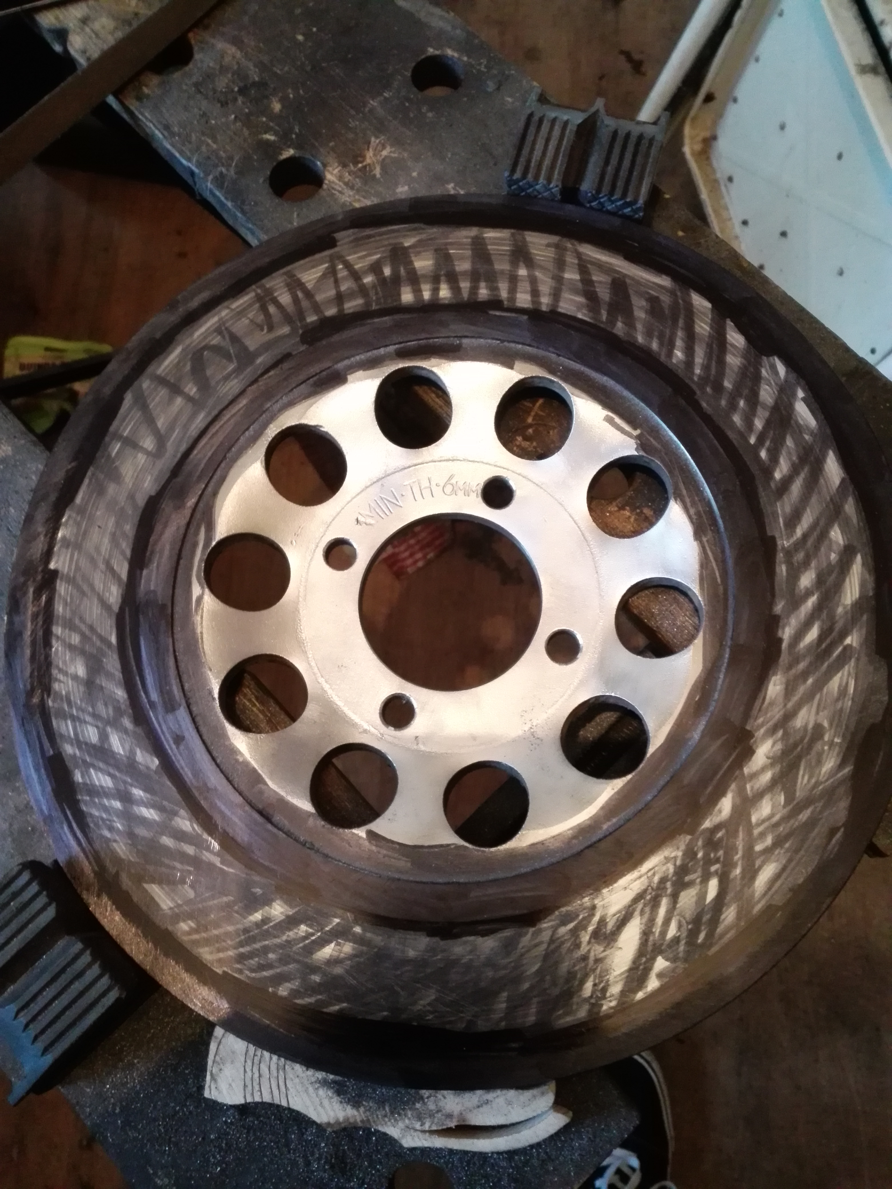
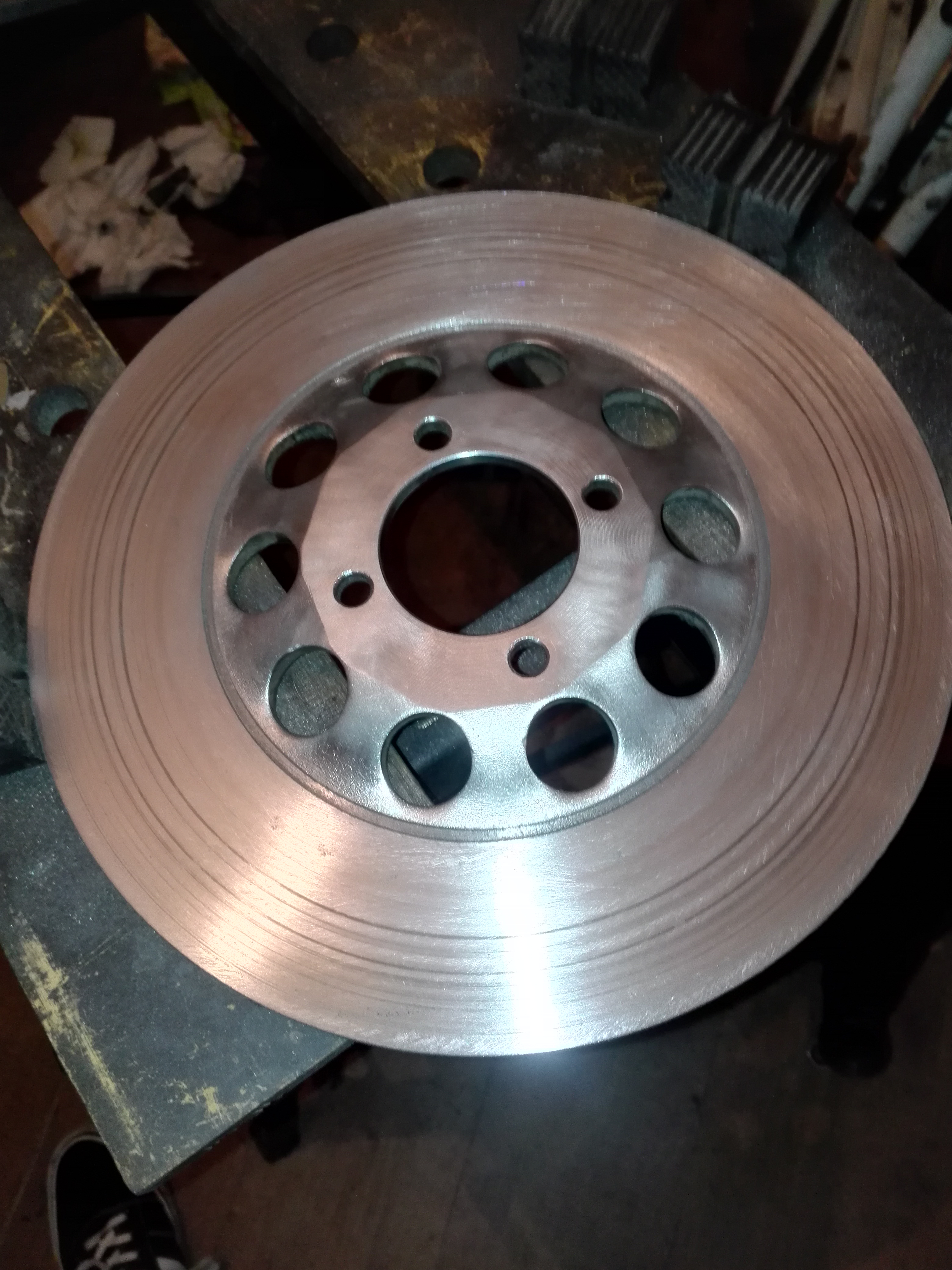
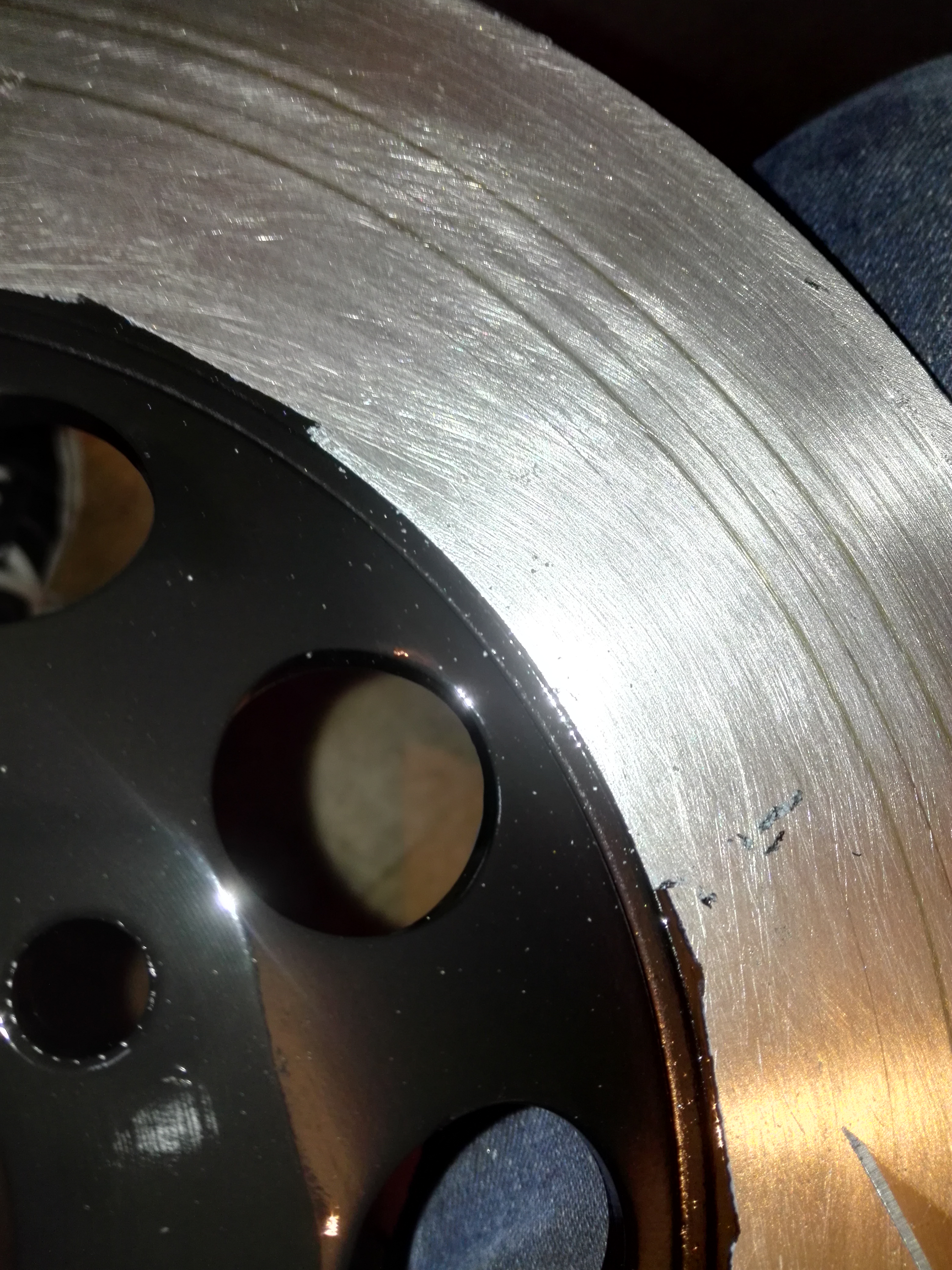
I’m trying to keep up the momentum but the season seems to get in the way a bit. Still, I am getting bits and pieces done. I turned my attention to the brake discs and started on the rear one.

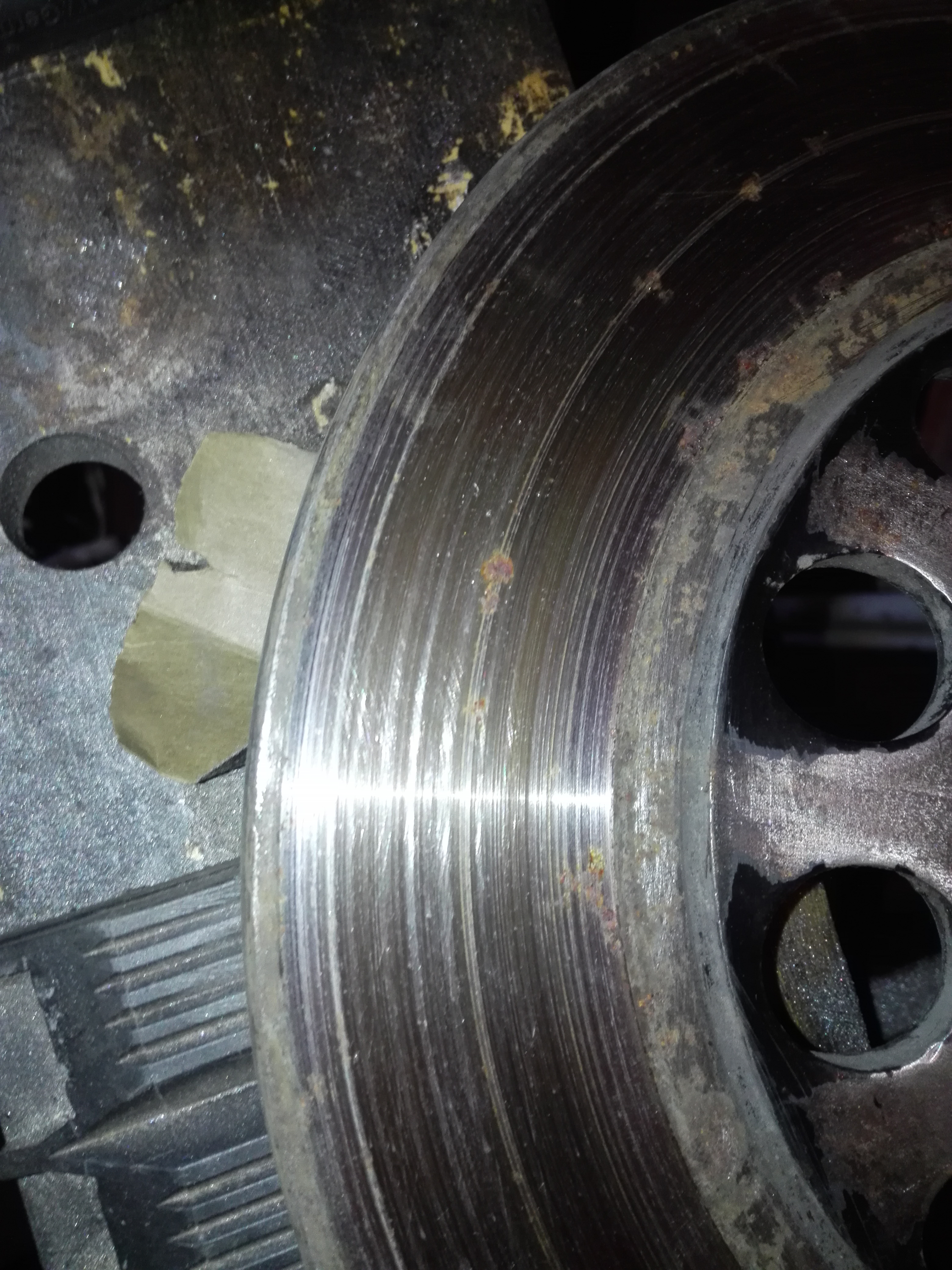
There is a bit of a ridge as expected and I decided to clean it up a bit. If you object to taking a file to a brake disc then look away now. Files may be a bit crude and imprecise but they have been part of precision engineering for ages. Don’t try this at home unless you are very confident. The first step is a wire brush to clean the centre and then it get covered in marker pen so I can see what I’m doing.
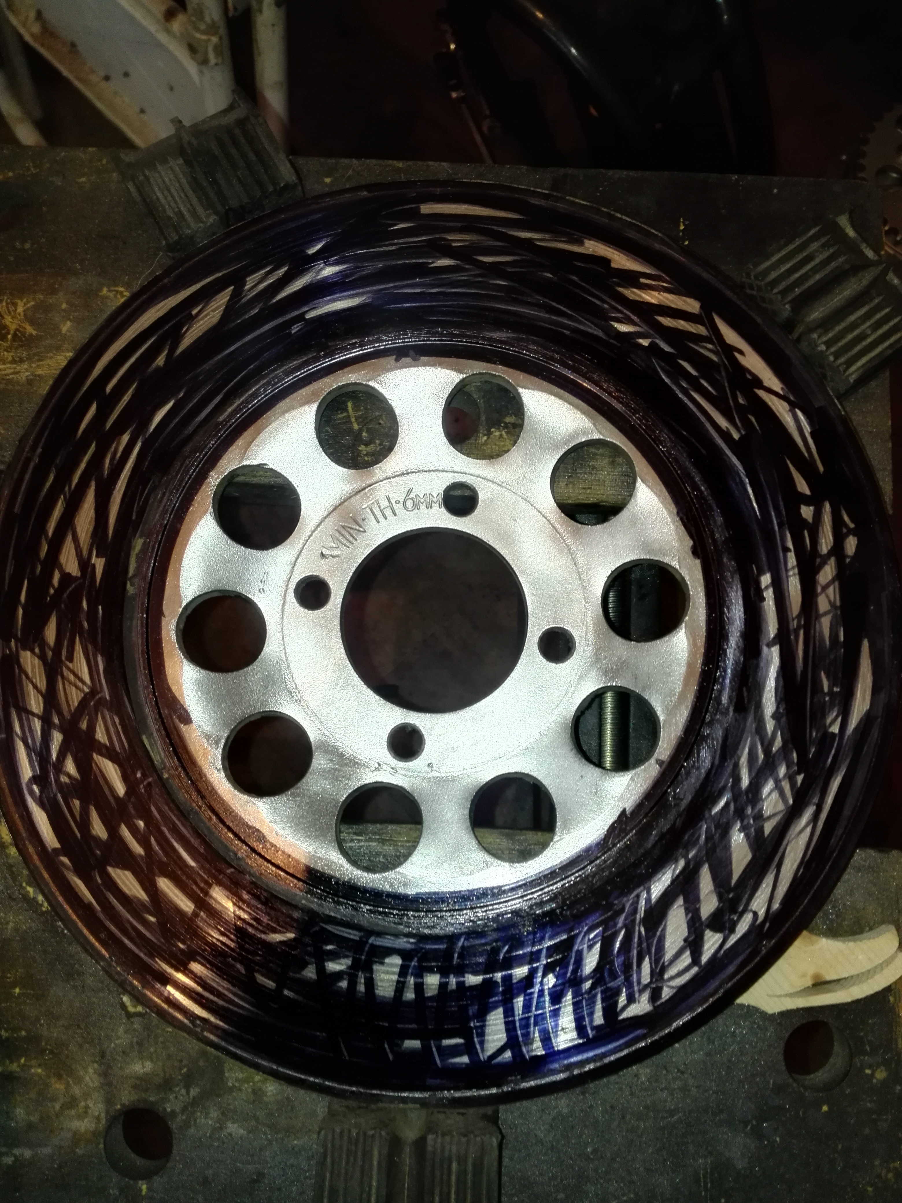
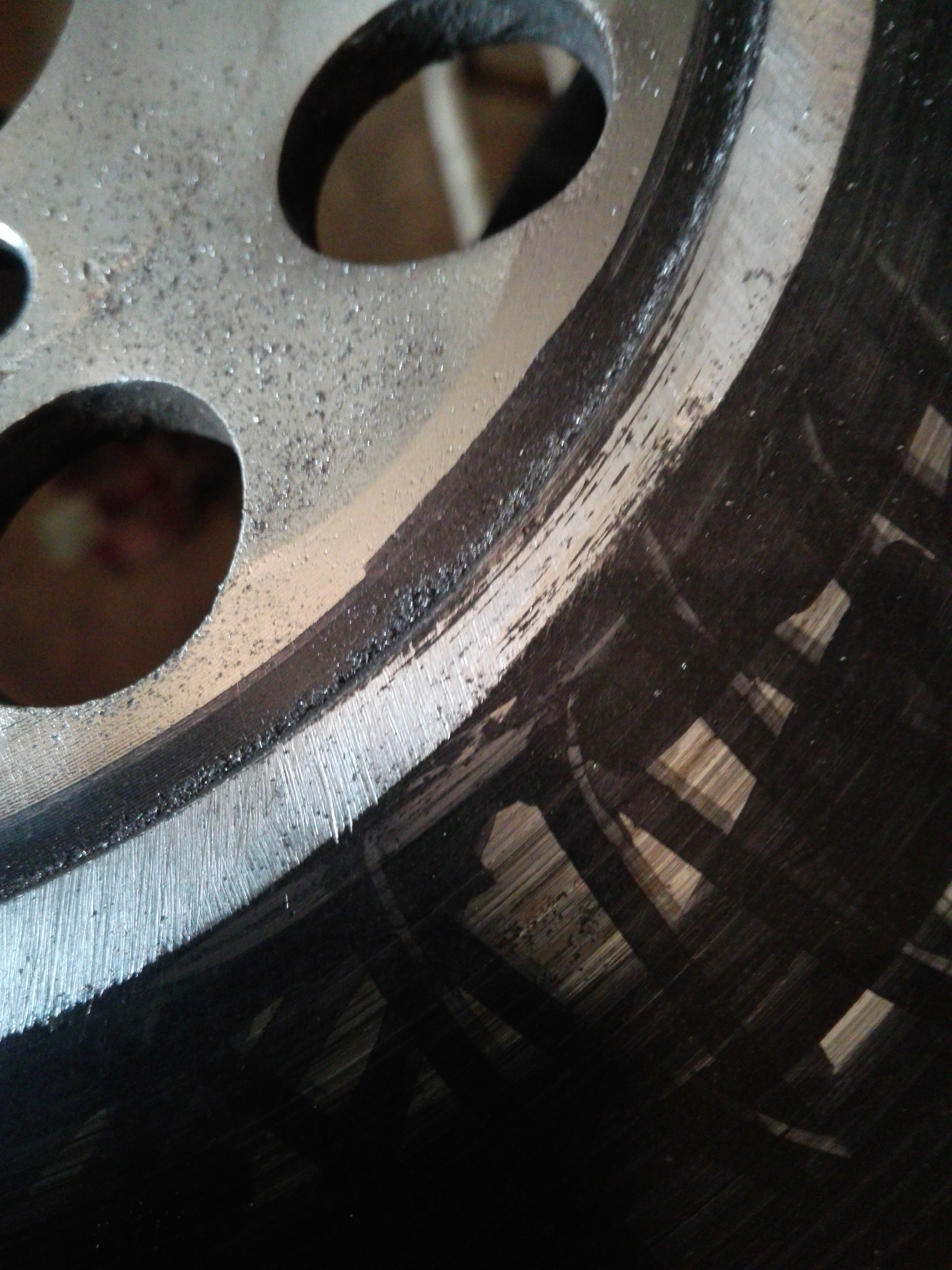
As you can see, I’m not taking anything off in the area where the pads have been in contact
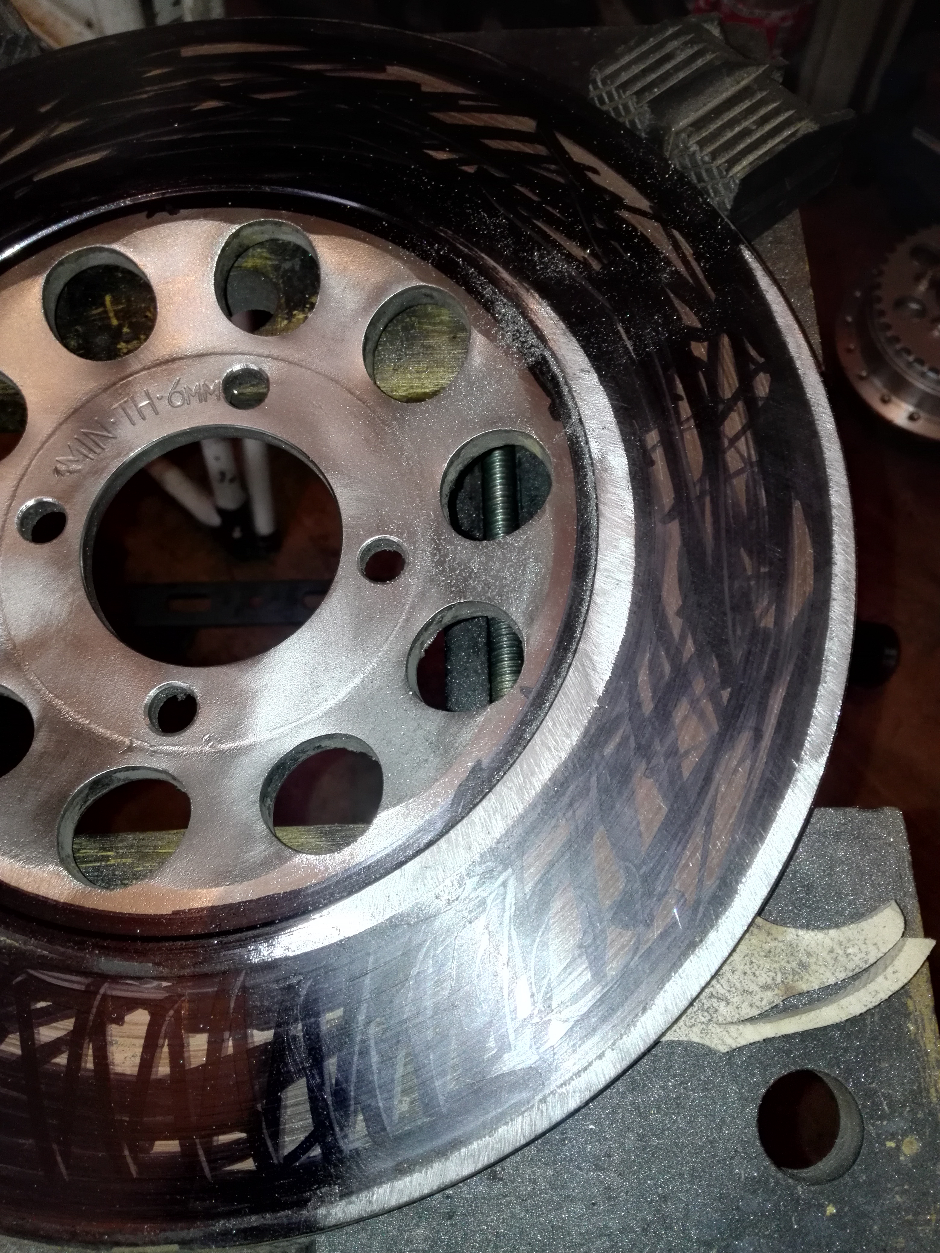
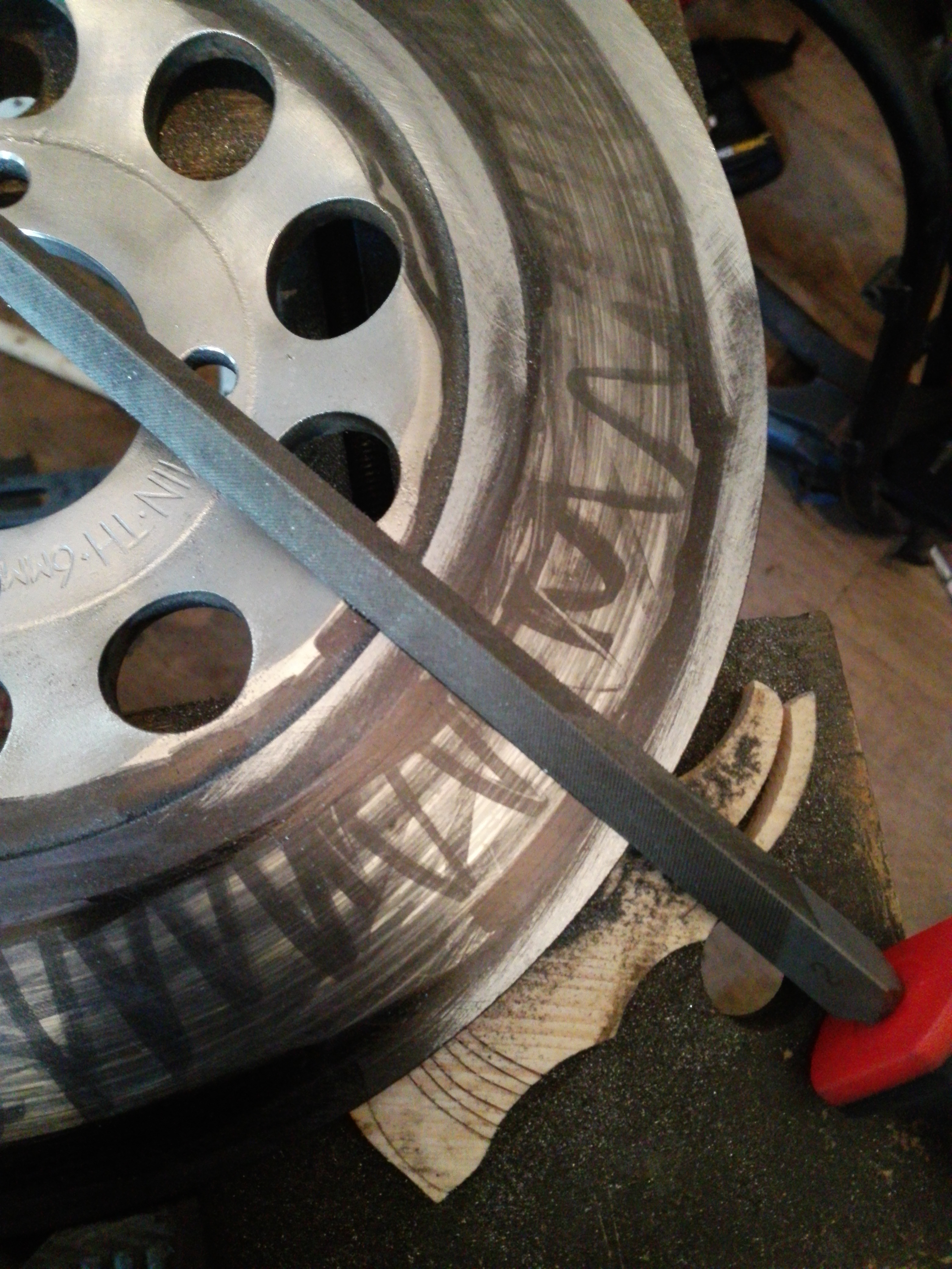
Here you can see how much metal is being removed
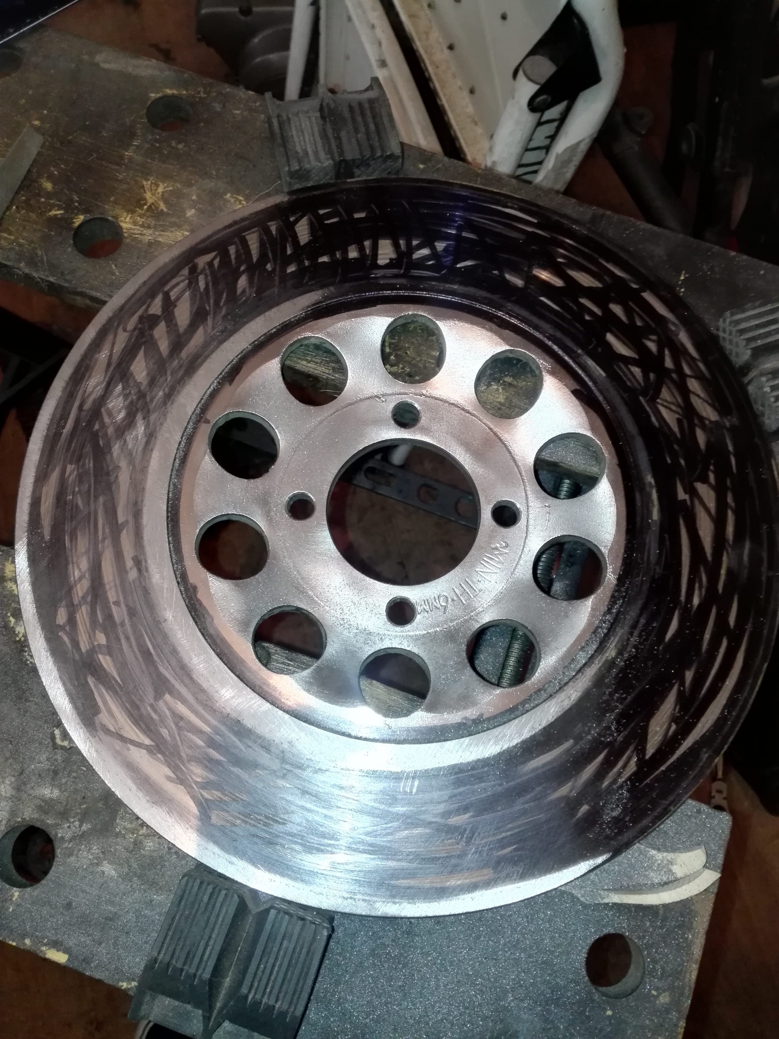
And that’s the first stage done.

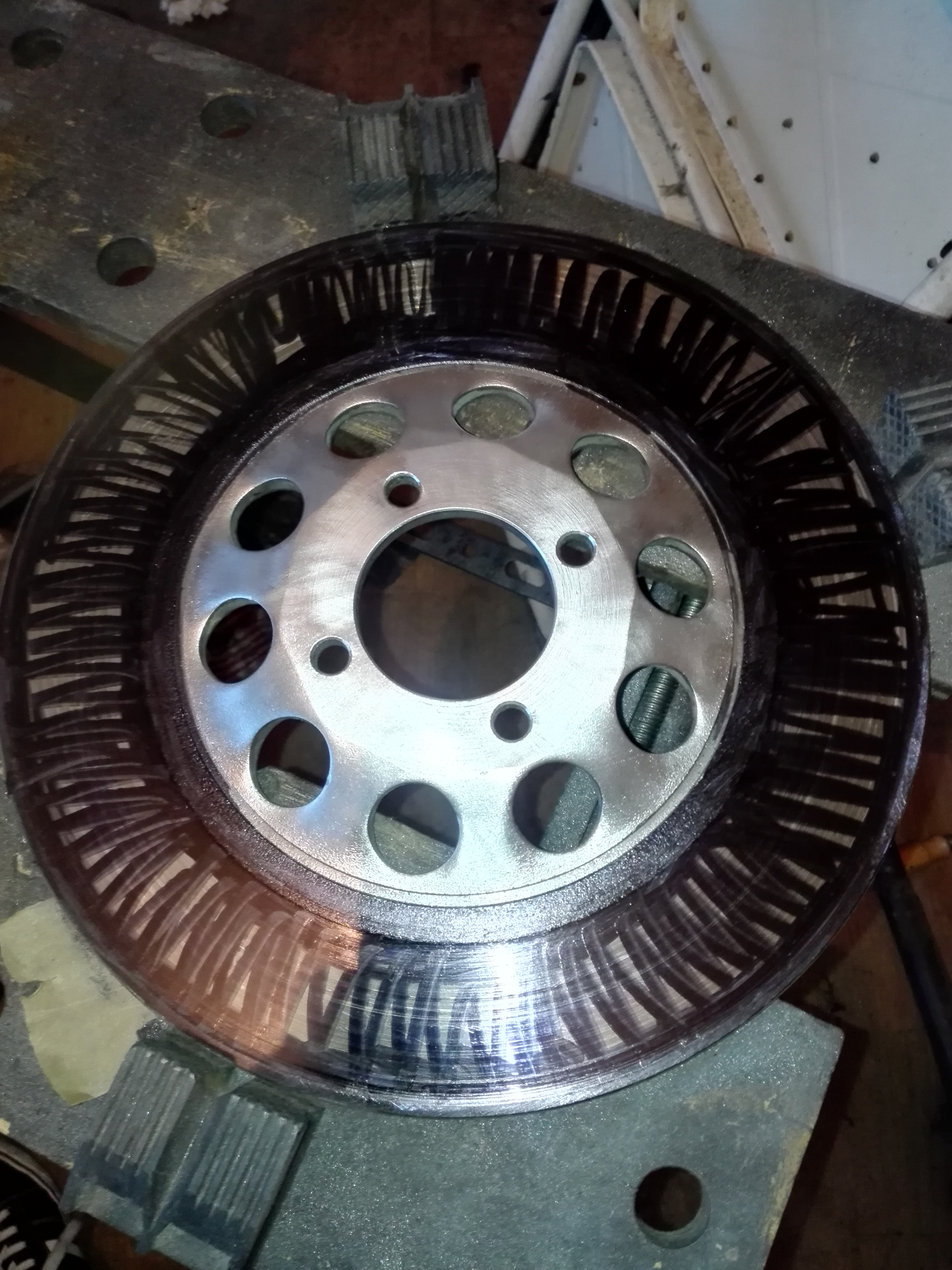
Next it gets a fresh coat of marker

And then another filing operation but in the opposite direction to help remove the deep scratches and flatten it all.
Then I coated it in marker again as I wanted to try a draw filing operation in the direction of rotation as a final smoothing process.
In process
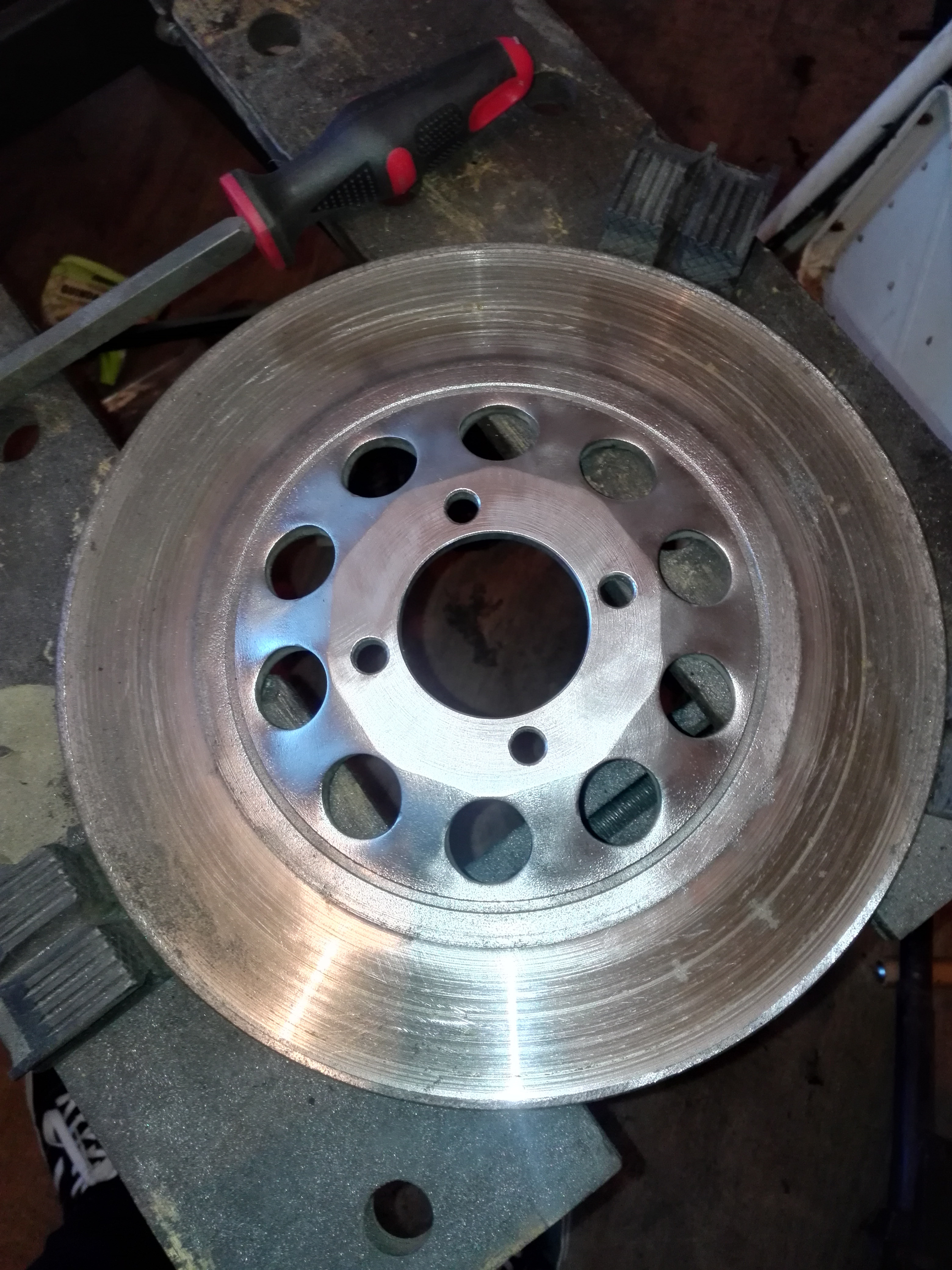
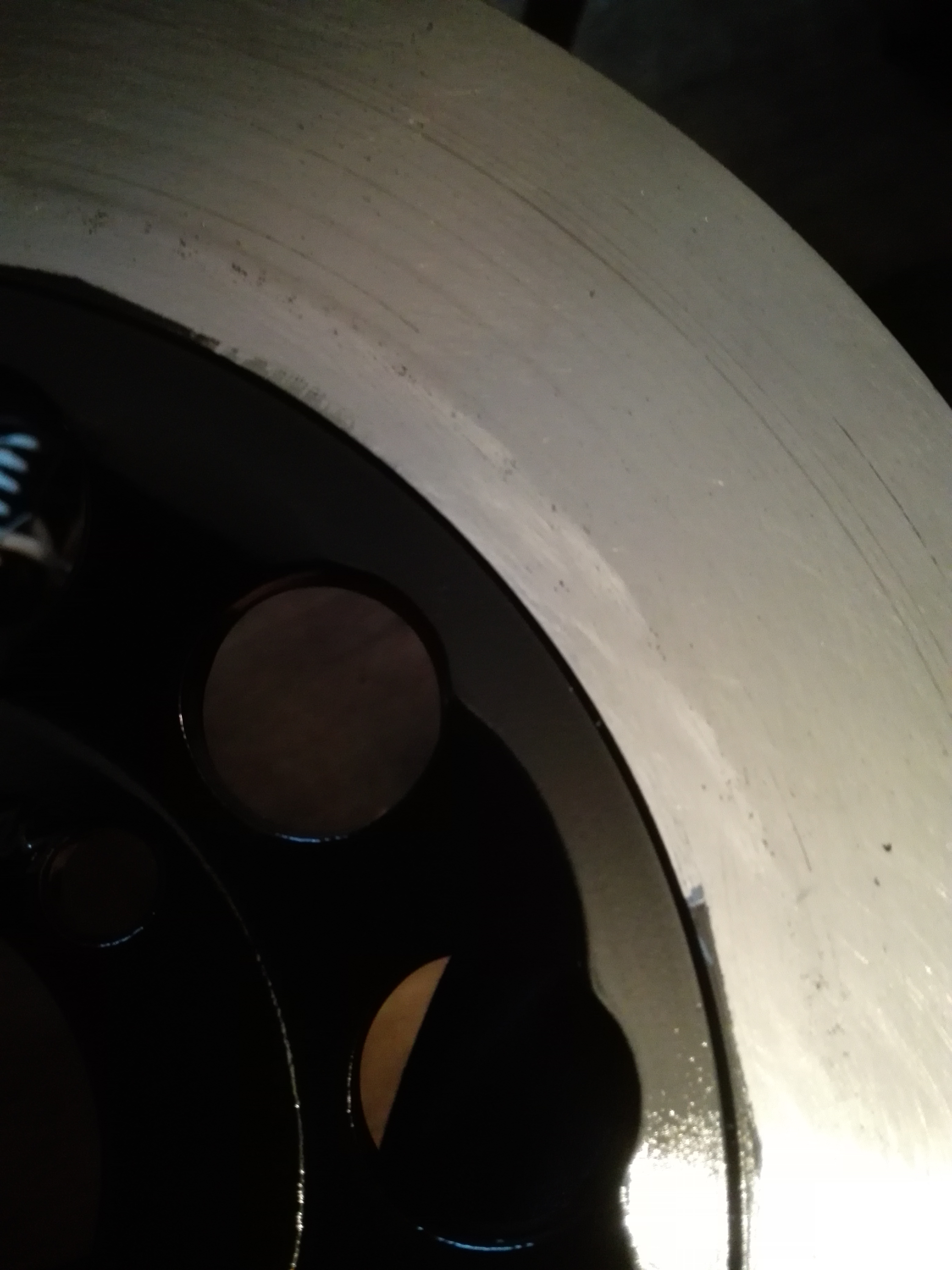
And done. As you can see I haven’t touched the area where the pads have been in contact.

After cleaning

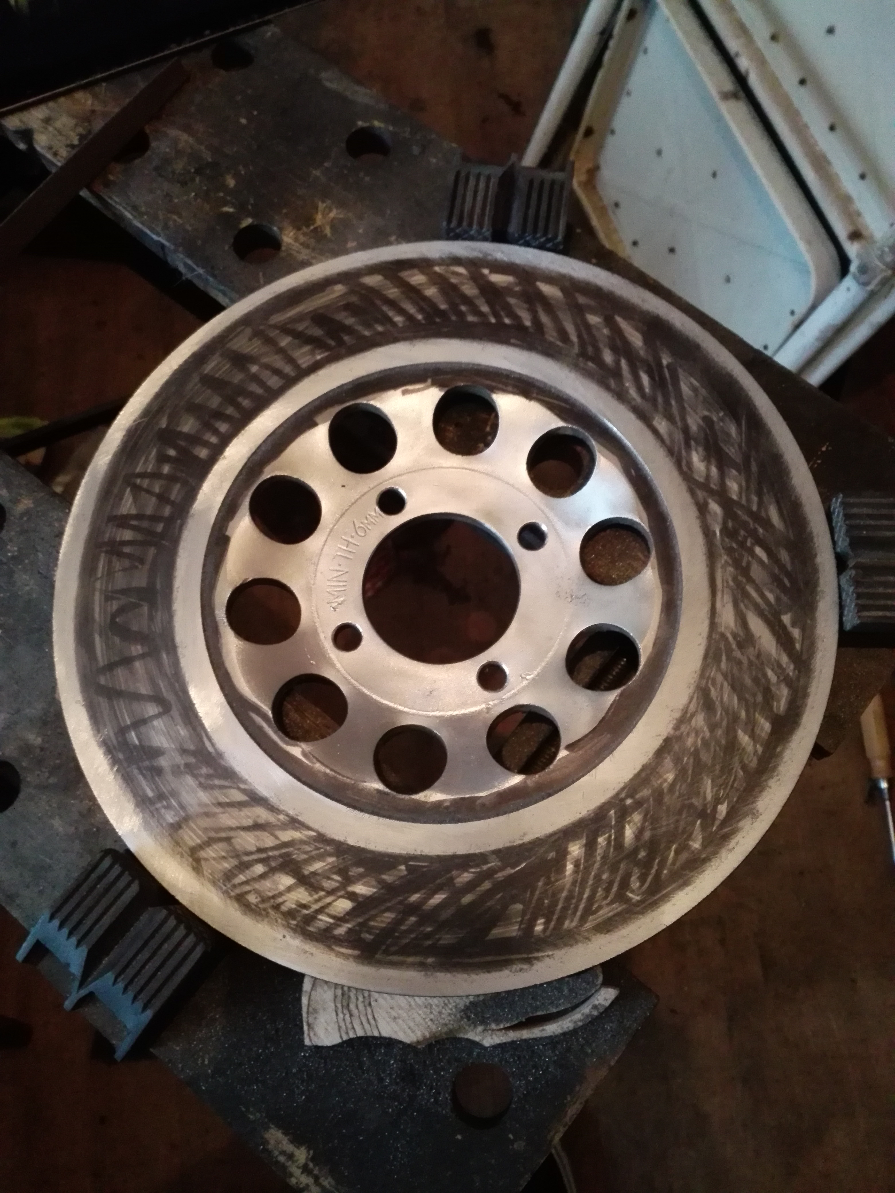
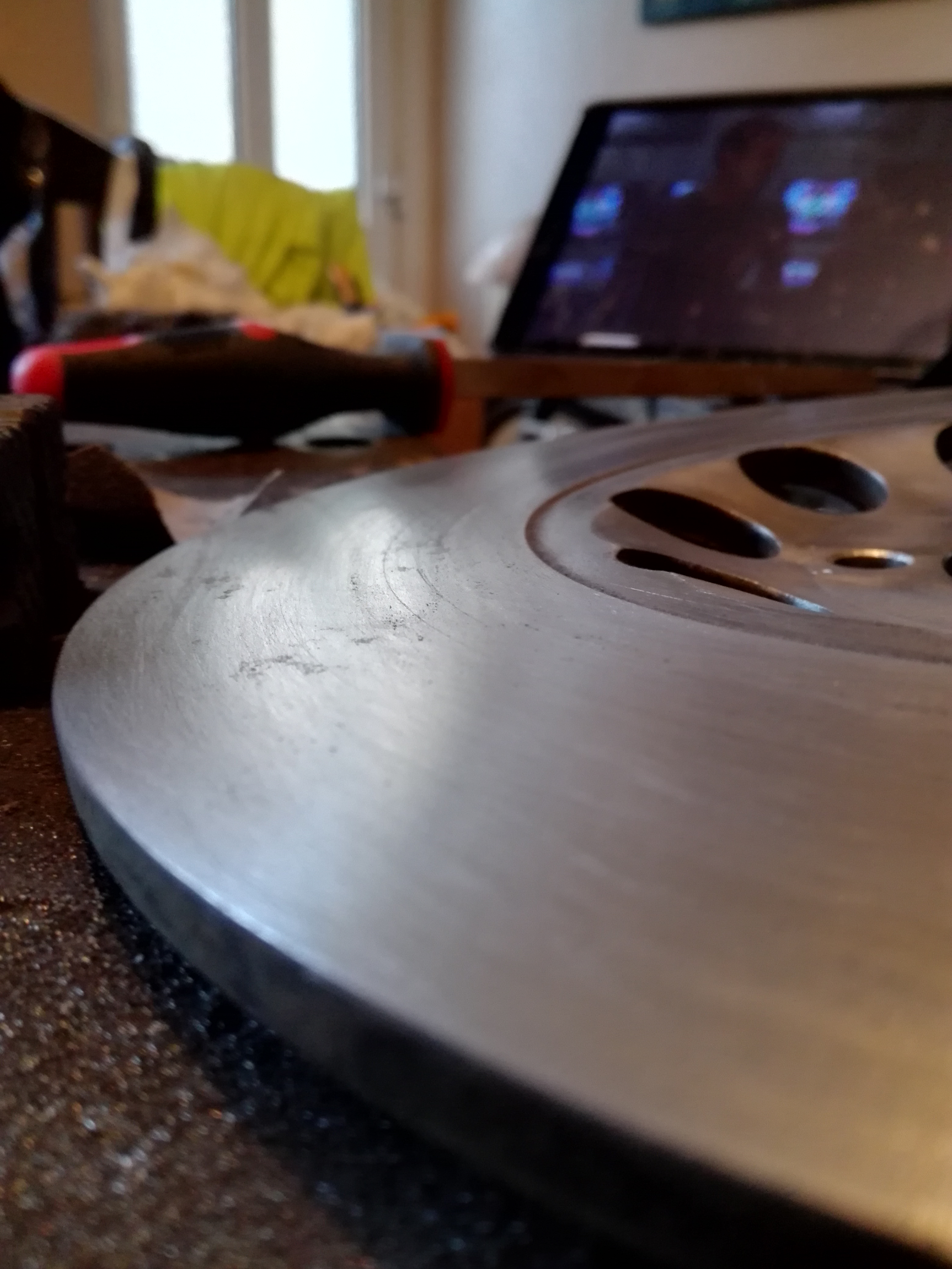
And after a bit of sanding to clean it all up.
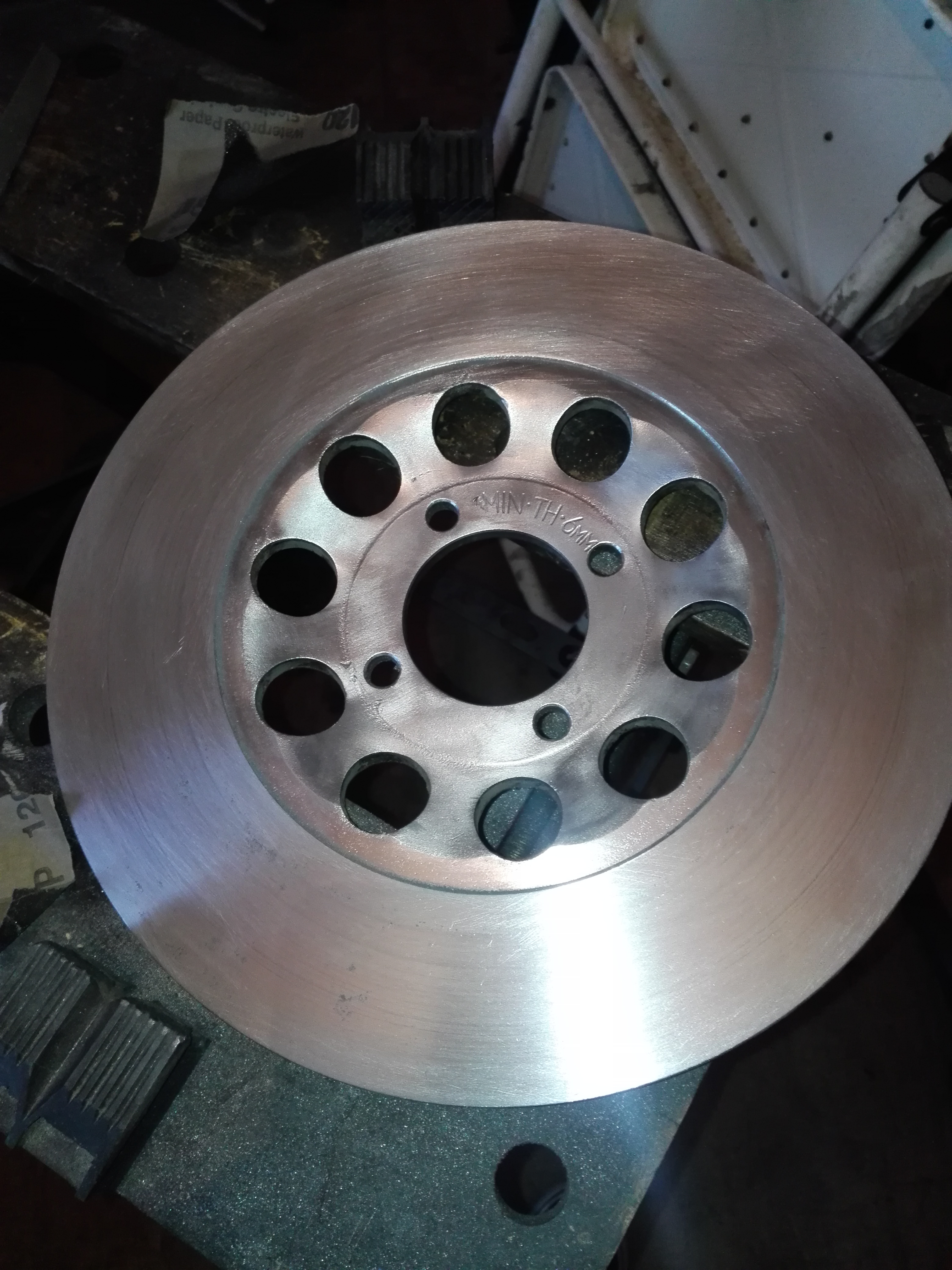
Its quite flat
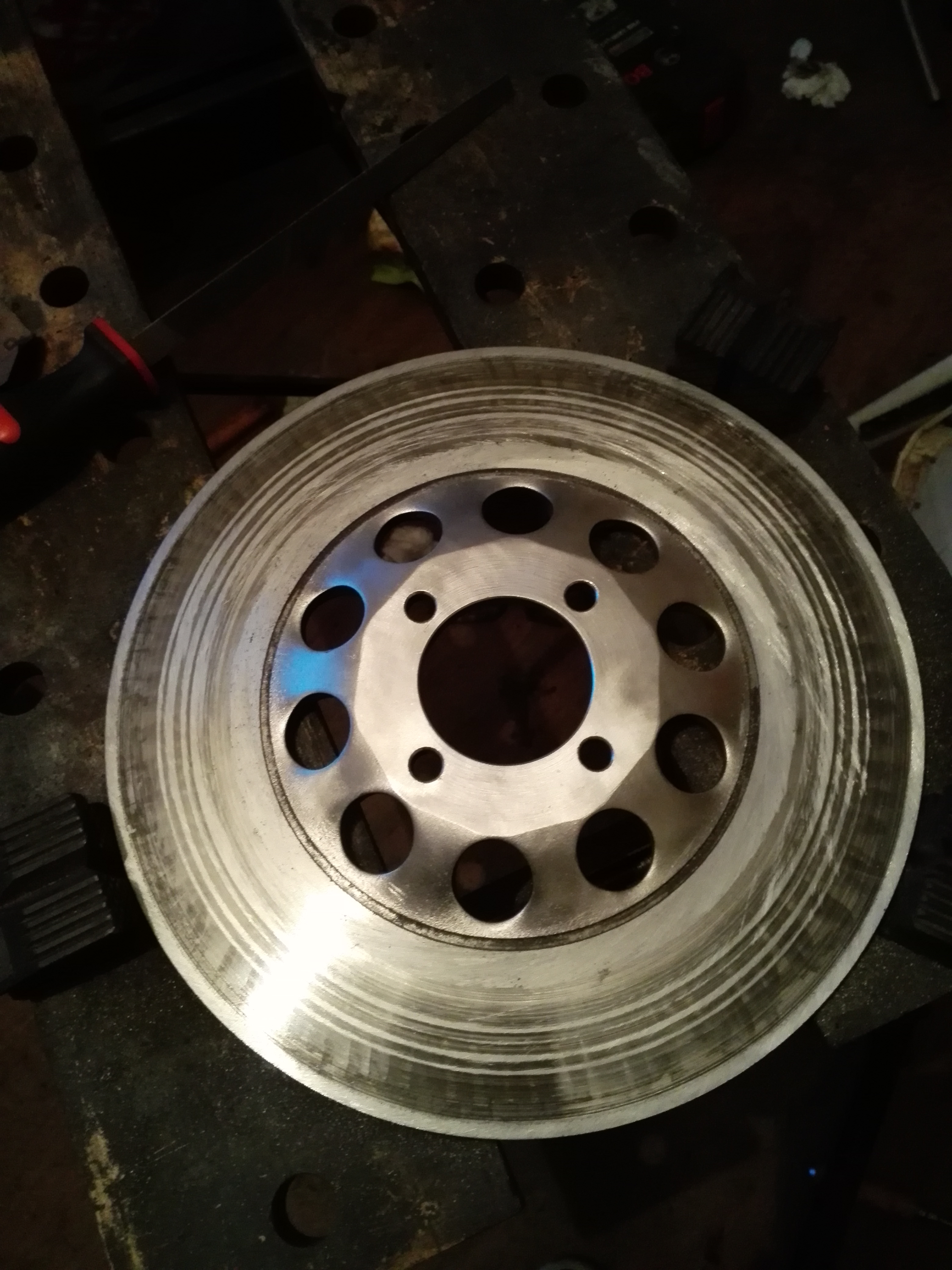
The back doesn’t look great either. Its a bit trickier with the raised centre.
First it gets wire brushed
Then more marker pen
I have to do the back at a weird angle but its working.

Op 1 complete
Second filing op complete. I cant draw file this side unfortunately.

After sanding.
Masked and painted
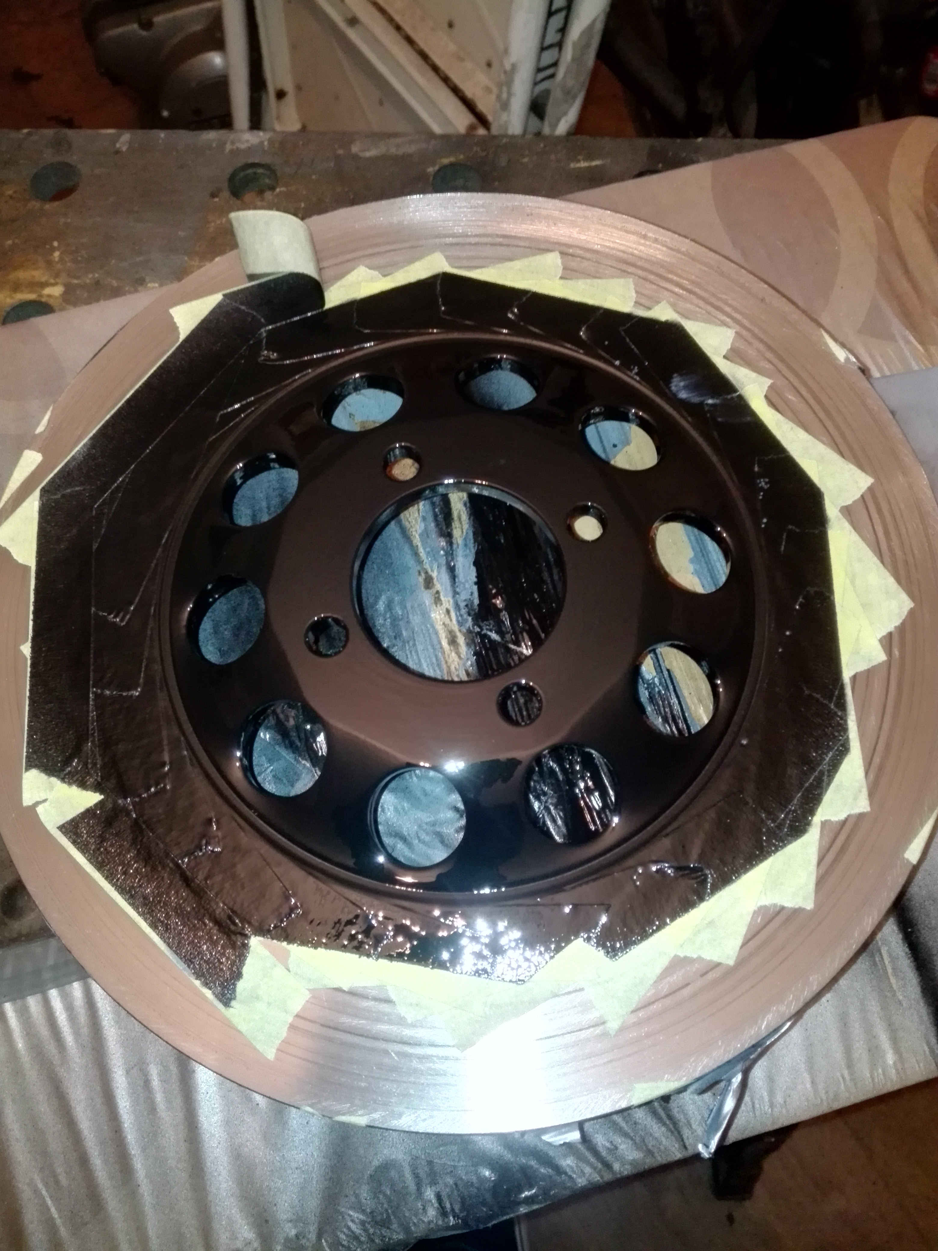
With the masking removed. I prefer to scrape paint edge.
Cleaning the edge with a knife blade
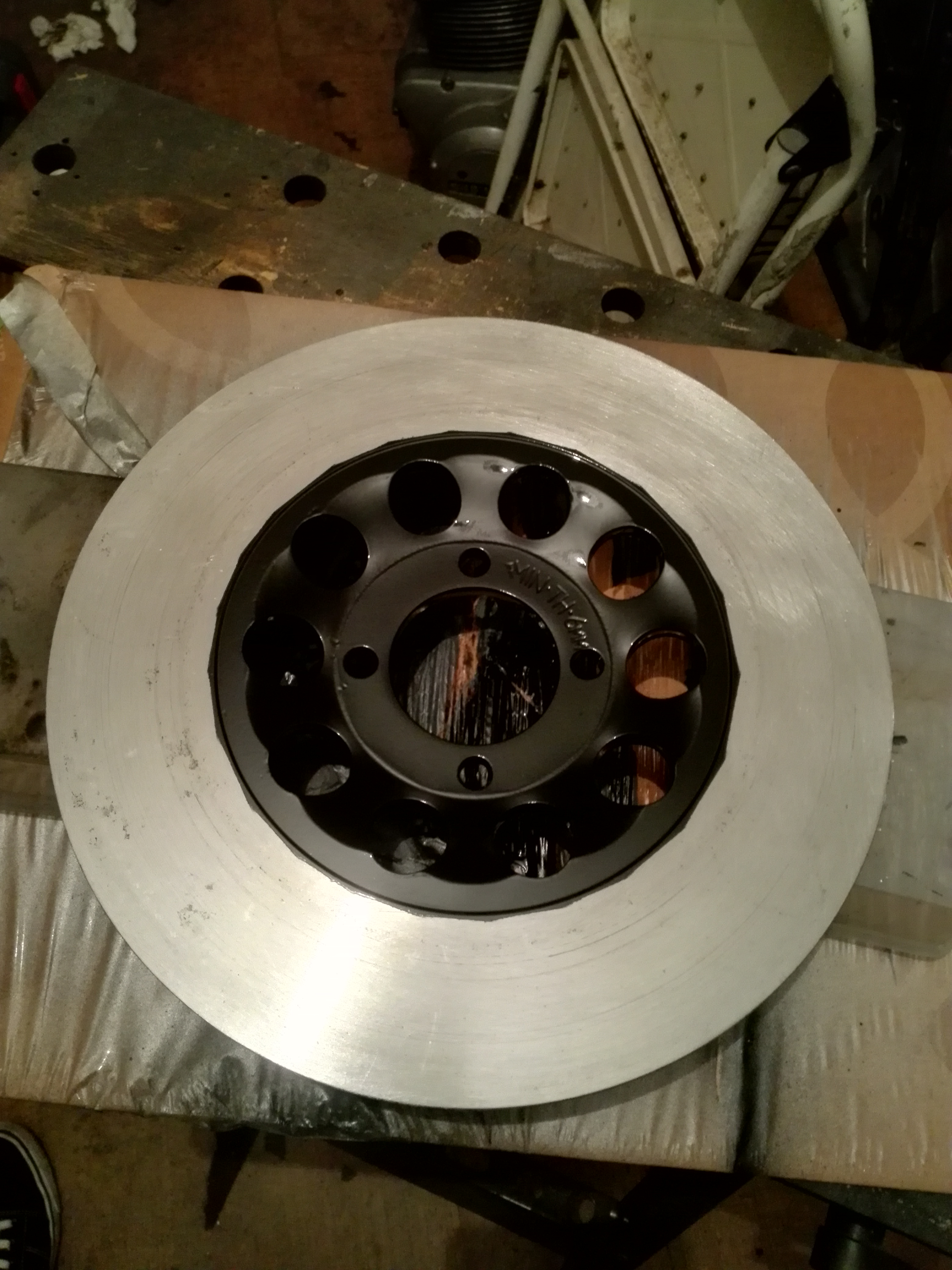
All done

And the back
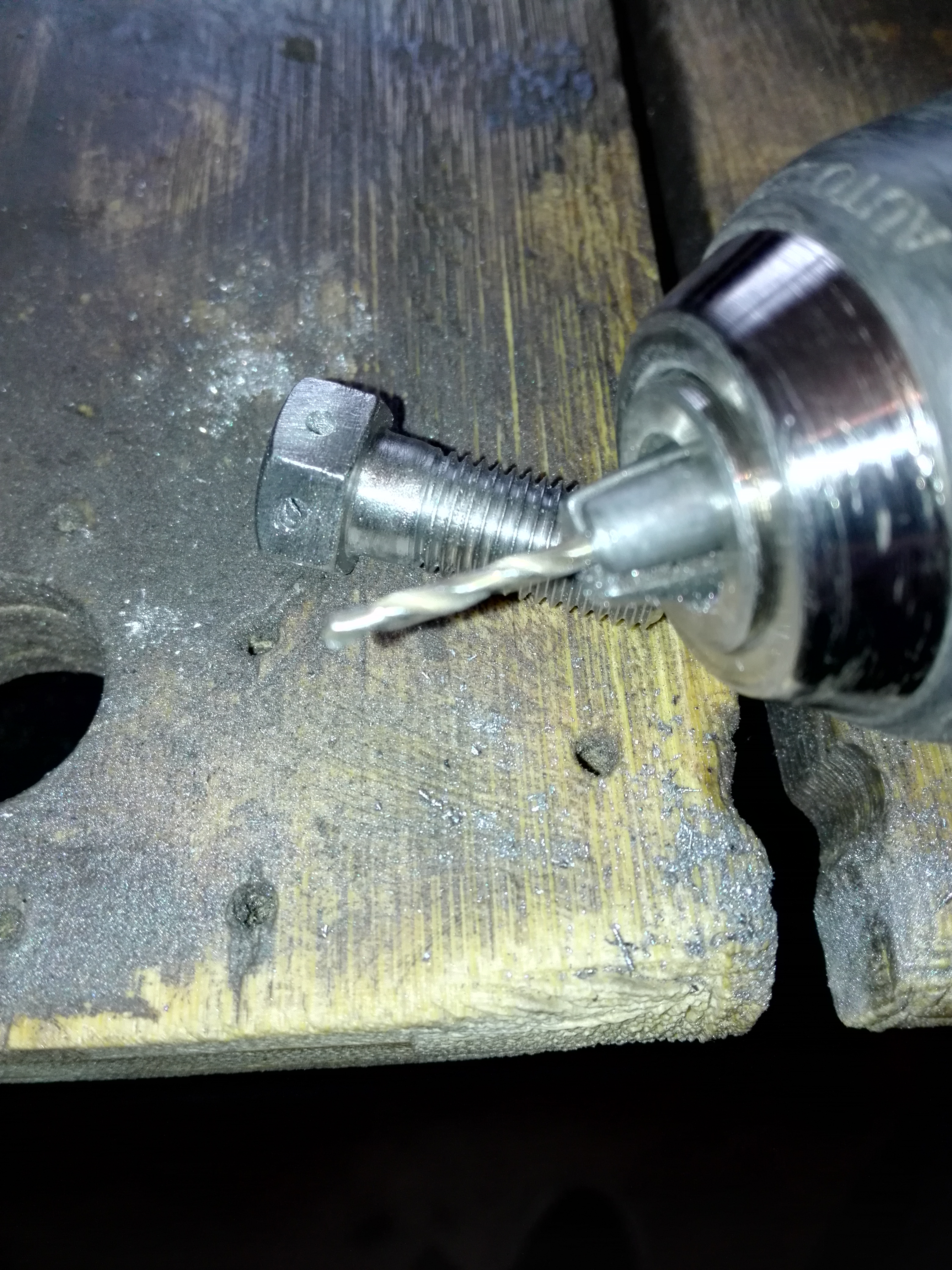
Now I just need to sort out the fasteners. Here they are after a wire brushing. I’m going to drill them for wires, same as the sprocket.
This is a bit low tech. I just centre punched them by eyeball using a countersink.
Drilling slow and steady with lots of stopping for sharpening. Quite tricky to sharpen these little drills. Despite my best efforts I broke 2 drills.
Last one
All done and countersunk ready for plating
After plating
Looking good but I’m going to make some washers.
The front disc got the same treatment and this is the result
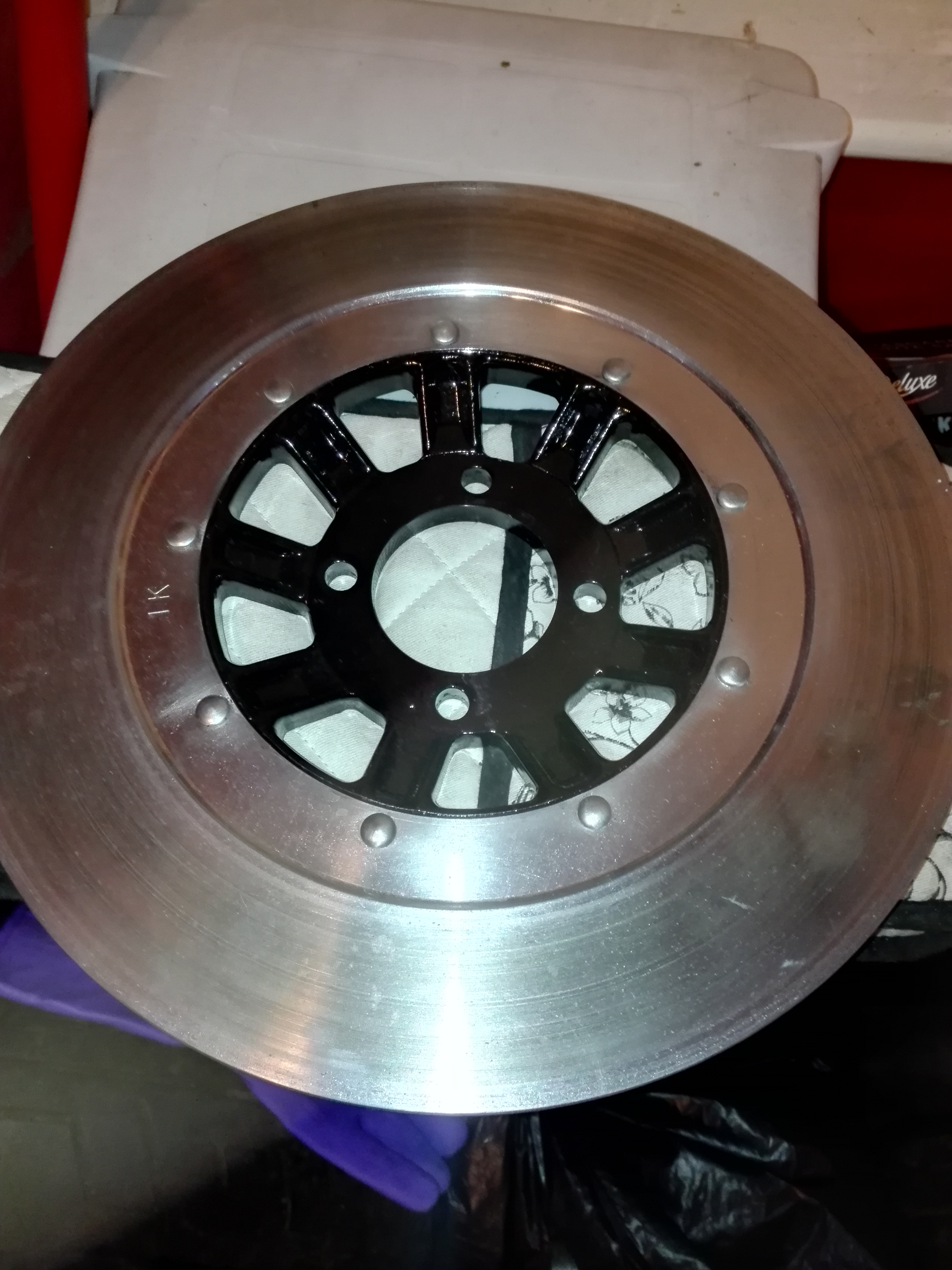
I still need to sort out the bolts for the front disc.
-
This reply was modified 7 years, 7 months ago by Ownthesky2010.
-
This reply was modified 7 years, 7 months ago by
-
AuthorPosts
- You must be logged in to reply to this topic.
